Thermally assisted magnetic head with optical waveguide and light shield

a technology of optical waveguides and magnetic heads, applied in the field of thermally assisted magnetic heads, can solve the problems of reducing the heating efficiency of magnetic recording media, and achieve the effects of reducing the light propagation efficiency, reducing the complexity of the whole apparatus, and reducing the yield

Active Publication Date: 2009-02-26
TDK CORPARATION
View PDF7 Cites 32 Cited by
  • Summary
  • Abstract
  • Description
  • Claims
  • Application Information

AI Technical Summary

Benefits of technology

[0009]For making the thermally assisted magnetic head described in Patent Document 1, it is necessary for the light source unit to be overlaid on and then secured to the surface (back face) of the slider on the side opposite from the medium-opposing surface. In this case, after testing the slider having the magnetic head part and the light source unit independently from each other, the slider and light source unit that have been found nondefective are secured to each other, whereby the thin-film magnetic head can be made with a favorable yield. Since the light source can be provided at a position distanced from the medium-opposing surface while being in the vicinity of the slider, there are substantially no problems concerning decreases in light propagation efficiency, complexity in the structure of the whole apparatus, and the like.

Problems solved by technology

This is because a deterioration in accuracy of alignment leads to a decrease in the heating efficiency of the magnetic recording medium, which may become a big problem when performing thermally assisted magnetic recording.

Method used


Image

  • Thermally assisted magnetic head with optical waveguide and light shield
  • Thermally assisted magnetic head with optical waveguide and light shield
  • Thermally assisted magnetic head with optical waveguide and light shield

Examples


Embodiment Construction

[0036]Preferred embodiments of the present invention will be explained with reference to the drawings. In the explanation, the same constituents or those having the same functions will be referred to with the same numerals or letters while omitting their overlapping descriptions. For easier viewing of the drawings, ratios of dimensions within and among the constituents in the drawings are arbitrary.

[0037][1] Structure of Hard Disk Drive

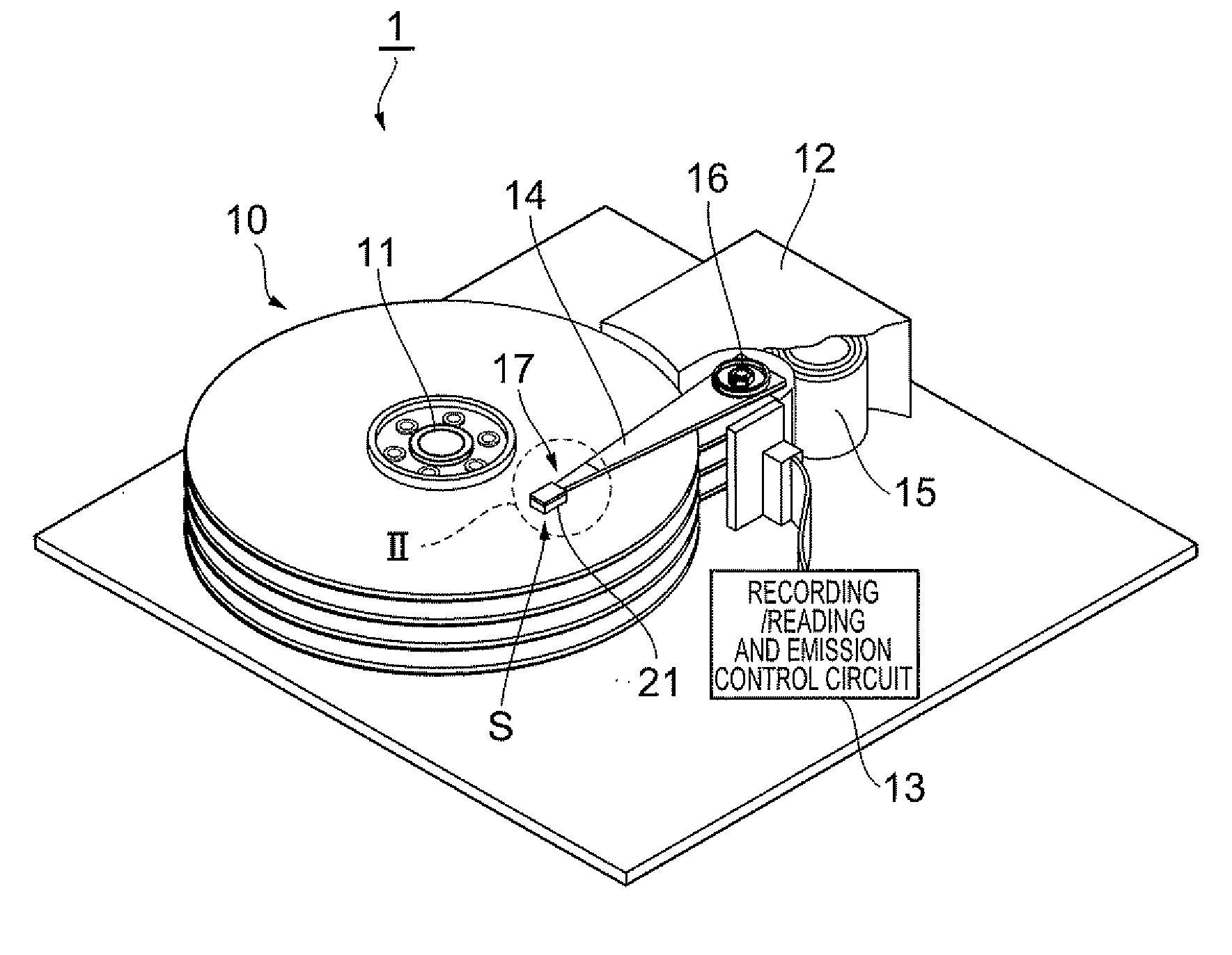
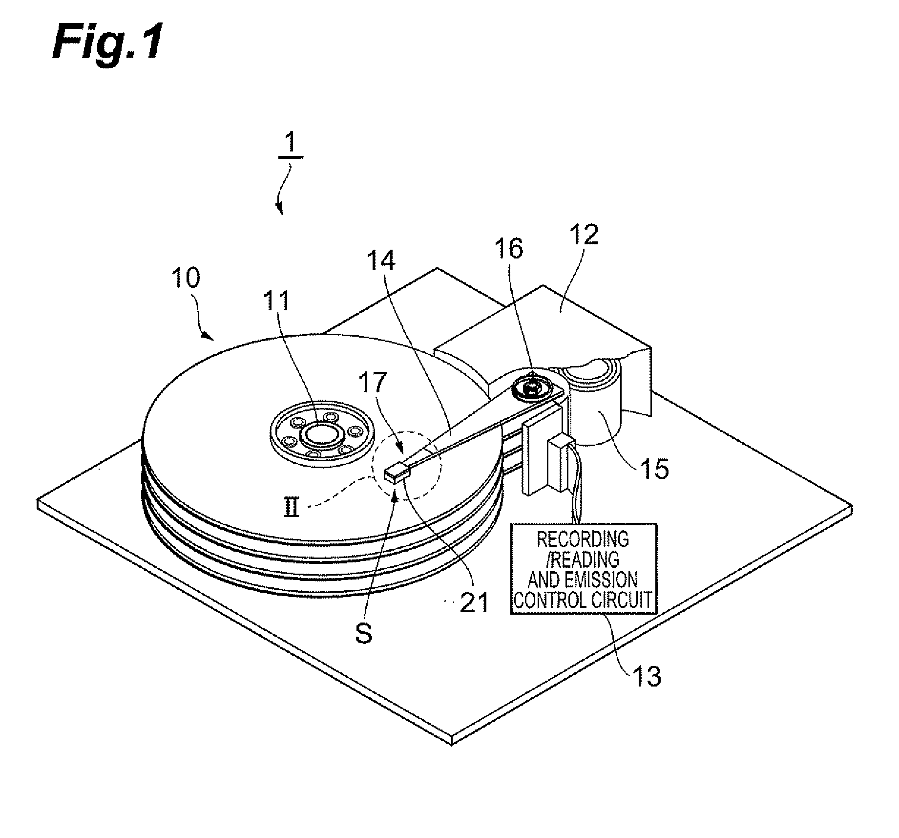
[0038]First, with reference to FIG. 1, the structure of a hard disk drive 1 will be explained. The hard disk drive 1 comprises a plurality of magnetic disks (magnetic recording media) 10 rotating about a rotary shaft of a spindle motor 11, an assembly carriage apparatus 12 for positioning thermally assisted magnetic heads 21 onto tracks, and a recording, reading, and emission control circuit 13 for controlling writing and reading actions by the thermally assisted magnetic heads 21 and regulating a laser diode 40 which is a light source for emitting la...


PUM

PropertyMeasurementUnit
thicknessaaaaaaaaaa
bevel angleaaaaaaaaaa
thicknessaaaaaaaaaa

Abstract

A thermally assisted magnetic head which can realize high-density writing onto magnetic recording media is provided.
The thermally assisted magnetic head includes a magnetic head part having a medium-opposing surface and a back face opposing the medium-opposing surface. The magnetic head part has a recording head part, an optical waveguide, and light shields. The optical waveguide extends along the opposing direction of the medium-opposing surface and back face. Each of the light shields extends along the opposing direction of the medium-opposing surface and back face and inhibits laser light from passing between the medium-opposing surface and back face. The optical waveguide and light shields are arranged on a first line when seen from the back face. When seen from the back face, the light shields oppose each other while interposing the first line therebetween and are arranged on a second line substantially orthogonal to the first line.

Description

BACKGROUND OF THE INVENTION[0001]1. Field of the Invention[0002]The present invention relates to a thermally assisted magnetic head which writes signals by a thermally assisted magnetic recording scheme, a head gimbal assembly (HGA) equipped with this thermally assisted magnetic head, and a hard disk drive equipped with the HGA.[0003]2. Related Background Art[0004]As hard disk drives have been increasing their recording density, thin-film magnetic heads have been required to further improve their performances. As the thin-film magnetic heads, those of composite type having a structure in which a magnetism detecting device such as a magnetoresistive (M) device and a magnetic recording device such as electromagnetic coil device are laminated have been in wide use, while these devices read / write data signals from / onto magnetic disks which are magnetic recording media.[0005]In general, a magnetic recording medium is a sort of discontinuous body in which magnetic fine particles are assem...

Claims


Application Information

Patent Timeline
Patent Type & Authority Applications(United States)
IPC IPC(8): G11B5/02
CPCG11B5/02G11B2005/0021G11B2005/0005G11B5/314
Inventor TANAKA, KOSUKEITO, YASUHIROSHIMAZAWA, KOJI
Owner TDK CORPARATION
Why Eureka
Try Eureka