Large field-of-view stray light PST (point source transmittance) testing method and device

A test device and test method technology, applied in the optical field, can solve the problems of low test accuracy, consistent test conditions and use conditions, burns on the surface of the primary mirror glass of a collimator, etc., and achieve the effect of breakthrough in test accuracy

Active Publication Date: 2012-10-24
XI'AN INST OF OPTICS & FINE MECHANICS - CHINESE ACAD OF SCI
View PDF4 Cites 30 Cited by
  • Summary
  • Abstract
  • Description
  • Claims
  • Application Information

AI Technical Summary

Problems solved by technology

[0006] At present, in the development of various aerospace cameras, the common stray light test methods are either the stray light coefficient test in the field of view of the black spot method, or the PST test of small aperture and small field of view. Although these test methods in the past can be used to a certain extent However, for high-sensitivity, diffraction-limited cameras, the previous test methods seem to have a small test range and low test accuracy, which cannot meet the reliability of the stray light suppression ability outside the field of view of this type of camera. Evaluate
[0007] Previous PST test systems used high-sensitivity PMT detectors as receivers and lasers as light sources to complete the test; if PMTs were used as detectors, the attenuation was often used due to their small dynamic range when detecting single photons. However, the use of attenuating sheet groups will cause measurement errors caused by multiple reflections of light energy inside the attenuating sheet assembly; at the same time, when PMT detects weak light, its stability is poor, and it is often affected by the environment. The influence of temperature and electromagnetic interference, so for the defects of PMT detectors, another weak light detection method should be studied
In addition, if a laser is used as a light source, although a higher output light energy can be obtained, in the test of different polychromatic light cameras, the test conditions cannot be consistent with the use conditions, and the light energy cannot be adjusted linearly in real time, that is, the output light energy is dynamic. The range is small; at the same time, the use of such a high-power laser tends to burn the glass surface of the collimator primary mirror

Method used


Image

  • Large field-of-view stray light PST (point source transmittance) testing method and device
  • Large field-of-view stray light PST (point source transmittance) testing method and device

Examples


Embodiment Construction

[0026] The invention provides a large field of view stray light PST testing method, the method comprising:

[0027] 1) The responsivity E of the illuminance at the entrance pupil when the target at the collection point is not in the optical system to be tested o ;

[0028] 2) Install and adjust the position of the optical system to be tested, and collect the responsivity E generated at the image plane of the optical system to be tested when the target passes through the optical system to be tested and is irradiated by stray light at different positions of the field of view. d (θ);

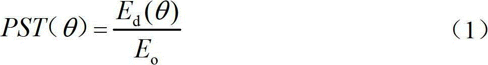
[0029] 3) According to the formula Calculate the PST(θ) value of the optical system under test with the field angle θ outside the field of view.

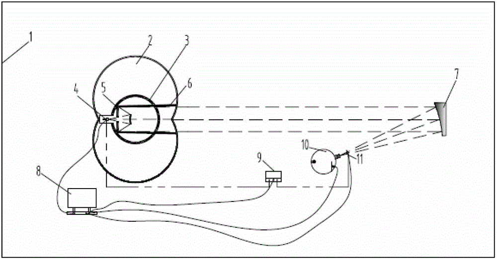
[0030] At the same time, the present invention provides a large-field stray light PST testing device based on the method while providing a large-field stray light PST test method. see figure 1 , the large field of view stray light PST device provided...


PUM


Abstract

The invention relates to a large field-of-view stray light PST (point source transmittance) testing method and a large field-of-view stray light PST testing device. The large field-of-view stray light PST testing device comprises a large dynamic range light source, a collimator, a clean room, a high-load turntable, an EMCCCD (electron multiplying charge coupled device) and a data acquisition and processing system, wherein the collimator is arranged on the path of emergent light of the large dynamic range light source; the EMCCD is arranged on the high-load turntable and is electrically connected with the data acquisition and processing system; the large dynamic range light source is electrically connected with the data acquisition and processing system; the high-load turntable is arranged on the path of emergent light after passing through the collimator; and the large dynamic range light source, the collimator, the high-load turntable, the EMCCD and the data acquisition and processing system are arranged in the clean room. The large field-of-view stray light PST testing method and the large field-of-view stray light PST testing device provided by the invention have the advantages that the stray light inhibiting ability of the lens hood of a astronautic camera can be effectively evaluated on the ground, the signal-to-noise ratio of the entire camera can be estimated, the astronautic camera can be guaranteed to pick up clear images after the astronautic camera is launched into the sky, the field of view is ultralarge and the accuracy is high.

Description

technical field [0001] The invention belongs to the field of optics, and relates to a method and device for testing the ability of suppressing stray light outside the field of view of an optical system, in particular to a test method and device mainly used for the suppression ability of stray light of various optical cameras before optical-mechanical docking, especially It is a performance test of weak target detection cameras in spaceflight before launch, and it is a large field of view stray light PST test method and device for the purpose of ensuring the optical-mechanical docking of the camera and clear imaging after launch into the sky. Background technique [0002] In recent years, with the development of high-sensitivity, low-detection-threshold detectors, there are higher requirements for the suppression of stray light in space optical systems, which requires higher precision in stray light measurement systems. [0003] Stray light radiation refers to the non-target ...

Claims


Application Information

Patent Timeline
Patent Type & Authority Applications(China)
IPC IPC(8): G01M11/02
Inventor 徐亮赵建科周艳刘峰张周峰胡丹丹张洁
Owner XI'AN INST OF OPTICS & FINE MECHANICS - CHINESE ACAD OF SCI
Why Eureka
Try Eureka