
Semiconductor device, chip module, and semiconductor module

Active Publication Date: 2018-07-12
AISIN AW CO LTD
View PDF1 Cites 5 Cited by
  • Summary
  • Abstract
  • Description
  • Claims
  • Application Information

AI Technical Summary

Benefits of technology

The patent describes a configuration for a semiconductor device and chip module that reduces impedance and enables stable power supply. The inner peripheral-side power supply terminal group is placed directly below the semiconductor chip and overlaps the target semiconductor element, allowing for a short wiring distance and low impedance. The surface layer power supply path formed on the surface layer wiring layer overlaps the inner peripheral-side power supply terminal group and the outer peripheral-side power supply terminal group, eliminating the need for through holes and reducing the impedance. This configuration prevents a decrease in the effective area of wiring and enables stable power supply.

Problems solved by technology

That is, the terminal arrangement is not suitable for device manufacturers that produce apparatuses utilizing such microcomputers and DSPs in many cases.
However, it is not profitable and not realistic in consideration of the development cost for the dedicated products etc.

Method used


Image

  • Semiconductor device, chip module, and semiconductor module
  • Semiconductor device, chip module, and semiconductor module
  • Semiconductor device, chip module, and semiconductor module

Examples


Embodiment Construction

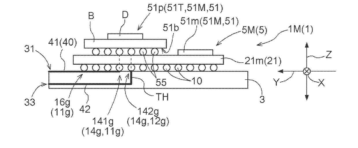
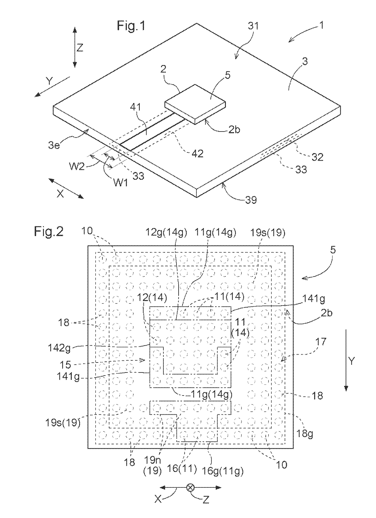
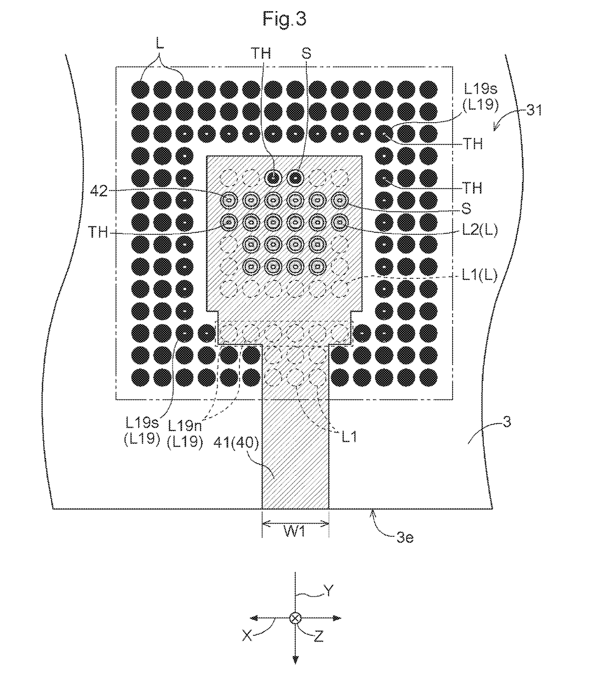
[0073]A semiconductor module and a semiconductor device according to an embodiment will be described below with reference to the drawings. As illustrated in FIG. 1, a semiconductor device 1 includes a circuit substrate 3 (main substrate) with a plurality of layers (31, 32, 33, 39) that have wiring layers in surface and inner layers and a semiconductor module 5 mounted on the circuit substrate 3. As illustrated in FIGS. 8 to 11, for example, the semiconductor module 5 is configured to include at least one semiconductor element 51 and a support substrate 21, on an upper surface 21a of which the semiconductor element 51 is supported and fixed. A plurality of terminals 10 (connection terminals) electrically connected to the semiconductor element 51 are disposed planarly on a lower surface 21b of the support substrate 21 to project from the lower surface 21b.

[0074]FIG. 8 schematically illustrates a general structure of the semiconductor module 5 (system LSI 5C) which is configured to in...


PUM


Abstract

Provided is a semiconductor device having a surface layer power supply path in a surface layer wiring layer, on which a chip module is mounted, of a main substrate that has a plurality of wiring layers and through holes, the surface layer power supply path supplying power to a semiconductor chip via an inner peripheral-side power supply terminal group and an outer peripheral-side power supply terminal group. The surface layer power supply path overlaps the inner peripheral-side power supply terminal group and the outer peripheral-side power supply terminal group as seen in the orthogonal direction, and is formed continuously so as to extend in a direction from a position at which the surface layer power supply path is connected to the inner peripheral-side power supply terminal group toward the outer peripheral side of the main substrate.

Description

CROSS REFERENCE TO RELATED APPLICATIONS[0001]This application is a National Stage of International Application No. PCT / JP2016 / 075578 filed Aug. 31, 2016, claiming priority based on Japanese Patent Application No. 2015-170409 filed Aug. 31, 2015, the contents of all of which are incorporated herein by reference in their entirety.TECHNICAL FIELD[0002]The present application relates to: a semiconductor device that includes a circuit substrate that has a plurality of wiring layers and through holes and a semiconductor module or a chip module; a chip module; and a semiconductor module.BACKGROUND ART[0003]Japanese Patent Application Publication No. 10-303562 (JP 10-303562 A) (Patent Document 1) discloses a technology of a circuit substrate that facilitates wiring and that enables stable power supply. In the case where a semiconductor module of a BGA (ball grid array) type with a multiplicity of connection terminals or the like is mounted on a circuit substrate, it is difficult to complete...

Claims


Application Information

Patent Timeline
IPC IPC(8): H01L23/12H05K3/46
CPCH01L23/12H05K3/46H01L2224/48091H01L2224/48227H01L2924/15311H01L2924/181H01L23/49838H01L23/50H01L25/072H01L23/49833H01L23/49816H01L2924/00014H01L2924/00012H05K3/429H01L24/48H05K1/0262H05K1/0263H05K1/112
Inventor NARUSE, TAKANOBU
Owner AISIN AW CO LTD
Learn More