Ac/dc power converter

Active Publication Date: 2018-07-12
COMMISSARIAT A LENERGIE ATOMIQUE ET AUX ENERGIES ALTERNATIVES
View PDF8 Cites 11 Cited by
  • Summary
  • Abstract
  • Description
  • Claims
  • Application Information

AI Technical Summary

Benefits of technology

The patent describes an AC-to-DC voltage conversion circuit that can efficiently convert AC voltage to DC voltage. The circuit includes four bidirectional switches connected in a H bridge configuration, with a transformer connected between the switches. The circuit can be controlled by a control circuit to switch between different configurations for the switches. The technical effect of this invention is to provide a more efficient and flexible AC-to-DC conversion circuit that can be used in various applications.

Problems solved by technology

A disadvantage of converters of this type lies in their relatively high cost and bulk, resulting from the high number of components that they comprise and from the size of these components.
Further, to limit switching losses in the DC / DC conversion stage, the operating frequency of the conversion stage (or cut-off frequency) is generally limited to a few hundreds of kHz, which limits possibilities of miniaturizing the DC / DC conversion stage, and in particular the isolation transformer.
Another disadvantage of converters of this type is that the presence of the rectifying stage comprising diodes significantly limits the converter efficiency.
Due to their architecture, and particularly due to the presence of the rectifying stage comprising diodes and of the low-pass filtering stage, converters of the type described hereabove do not provide such a reversibility.
However, as in conventional converters, switching losses in the switched-mode conversion stage in practice prevent the increase of the switching frequency of the switches beyond a few hundreds of kHz, which limits possibilities of miniaturizing the system, and in particular the isolation transformer.

Method used


Image

  • Ac/dc power converter
  • Ac/dc power converter
  • Ac/dc power converter

Examples


first embodiment

ture

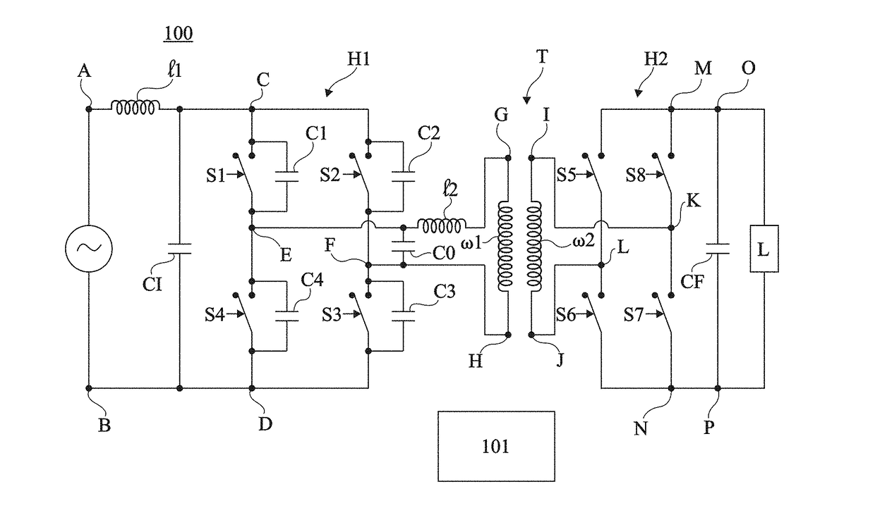
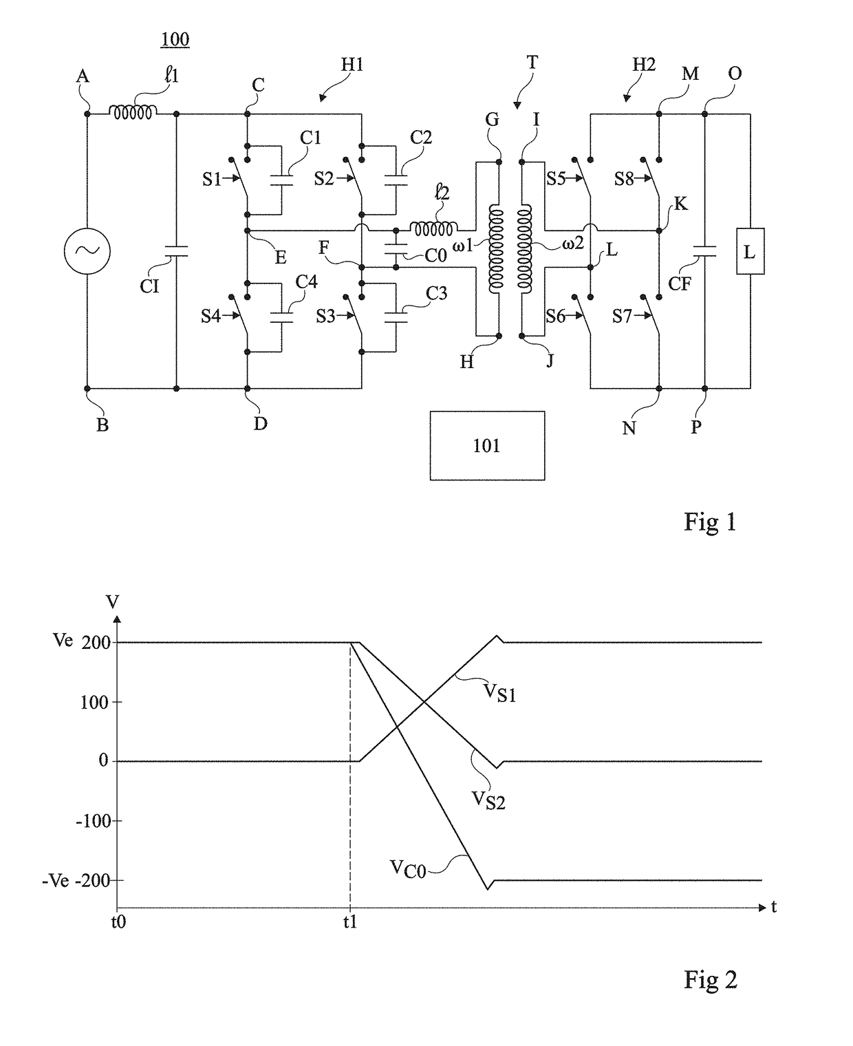
[0064]FIG. 1 is a wiring diagram of an example of an AC / DC converter 100 according to a first embodiment.

[0065]Converter 100 comprises a first controlled H bridge H1, or primary bridge, followed by an isolation transformer T, followed by a second controlled H bridge H2, or secondary bridge.

[0066]Bridge H1 is formed of four switches, bidirectional in terms of current and of voltage, S1, S2, S3, and S4, for example, identical (to within manufacturing dispersions), each comprising two main conduction nodes and at least one control node. Switches S1 and S4 are series-coupled, by their conduction nodes, between input nodes C and D of the bridge. Switches S2 and S3 are series-coupled, by their conduction nodes, between nodes C and D, in parallel with the branch comprising switches S1 and S4. Junction point E of switches S1 and S4 defines a first output node of the bridge, and junction point F of switches S2 and S3 defines a second output node of the bridge. More particularly, in the s...

second embodiment

re

[0109]FIG. 5 is a wiring diagram of an example of an AC / DC converter 500 according to a second embodiment.

[0110]Converter 500 comprises a first controlled H bridge H1, or primary bridge, followed by an isolation transformer T, comprising a primary winding W1 and a secondary winding W2, magnetically coupled, followed by a second controlled H bridge H2, or secondary bridge.

[0111]Bridge H1 is formed of four switches, bidirectional in terms of current and of voltage, S1, S2, S3, and S4, for example, identical (to within manufacturing dispersions), each comprising two main conduction nodes and at least one control node. Switches S1 and S4 are series-coupled, by their conduction nodes, between input nodes C and D of the bridge. Switches S2 and S3 are series-coupled, by their conduction nodes, between nodes C and D, in parallel with the branch comprising switches S1 and S4. Junction point E of switches S1 and S4 defines a first output node of the bridge, and junction point F of switches ...


PUM


Abstract

An AC / DC conversion circuit, including: four bidirectional switches forming an H bridge; a capacitor connected between input nodes of the bridge; a capacitor connected between output nodes of the bridge; and a control circuit capable of controlling the bridge alternately to a first configuration where first and second diagonals of the bridge are respectively conductive and non-conductive, and to a second configuration where the first and second diagonals are respectively non-conductive and conductive, the control circuit being capable, during a phase of transition between the first and second configurations, of: turning off the switches of the first diagonal; and for each switch of the second diagonal, turning on the switch only when the voltage thereacross takes a zero value.

Description

[0001]This application claims the priority benefit of French patent application number 17 / 50210, the content of which is hereby incorporated by reference in its entirety to the maximum extent allowable by law.BACKGROUND[0002]The present disclosure relates to power converters, and more particularly aims at an AC / DC converter, that is, a converter capable of converting an AC voltage into a DC voltage.[0003]DISCUSSION OF THE RELATED ART[0004]An AC / DC converter conventionally comprises a stage for rectifying the AC voltage applied at its input, comprising one or a plurality of diodes, followed by a stage of low-pass filtering of the rectified AC voltage delivered by the rectifying stage, followed by a stage of DC / DC conversion of the DC voltage delivered by the low-pass filtering stage, typically a switched-mode conversion stage comprising one or a plurality of controlled switches and an isolation transformer.[0005]A disadvantage of converters of this type lies in their relatively high ...

Claims


Application Information

Patent Timeline
IPC IPC(8): H02M7/219H02M1/42H02M7/155H03K17/30H03K17/06H02M1/00H02M7/5388H03K17/74
CPCH02M7/219H02M7/155H02M1/4258H03K17/06H03K17/302H02M1/4233H02M2007/2195H02M2001/0058H03K17/74H01L2924/13091H02M7/5388H02M7/4807Y02B70/10H02M1/0058H02M7/2195
Inventor STERNA, LEOLADHARI, OTHMANFERRIEUX, JEAN-PAULFREY, DAVIDJEANNIN, PIERRE-OLIVIER
Owner COMMISSARIAT A LENERGIE ATOMIQUE ET AUX ENERGIES ALTERNATIVES
Why Eureka
Try Eureka