Parallel-in converter for directly-driving wind power generation system

A technology of converters and power grids, which is applied in the direction of conversion equipment for intermediate conversion to DC, conversion of AC power input to AC power output, electrical components, etc., which can solve the problems that hinder the promotion of direct-drive wind turbines, and the price is expensive , Difficulty in manufacturing energy storage inductors, etc.

Inactive Publication Date: 2009-06-24
刘建政
View PDF2 Cites 56 Cited by
  • Summary
  • Abstract
  • Description
  • Claims
  • Application Information

AI Technical Summary

Problems solved by technology

[0003] Among the various converter schemes of the direct-drive wind power generation system, the structure control of the back-to-back converter widely studied at present is relatively complicated, and the cost is high, which hinders the promotion speed of the direct-drive wind power generation set; and the simple The converter structure composed of an uncontrolled rectifier circuit and a PWM inverter circuit has certain practicability, but this structure cannot effectively control the wind generator, which limits its available wind speed range, and the wind turbine required Multiple control objectives such as maximum power tracking control and grid-connected current control are difficult to balance; in this case, a new scheme of introducing a DC-DC structure Boost circuit into the DC link of the converter It can overcome the above shortcomings, but it also introduces certain problems: the traditional DC-DC Boost circuit needs a large energy storage inductance, and it needs to be equipped with a bulky and cumbersome inductance device; at the same time, under high-power application conditions , the current flowing in the energy storage inductor is a unidirectional triangular wave current. The current not only has a DC comp

Method used


Image

  • Parallel-in converter for directly-driving wind power generation system
  • Parallel-in converter for directly-driving wind power generation system
  • Parallel-in converter for directly-driving wind power generation system

Examples


Embodiment 1

[0045] Example 1: 20kW direct drive wind power converter (diode rectification mode)

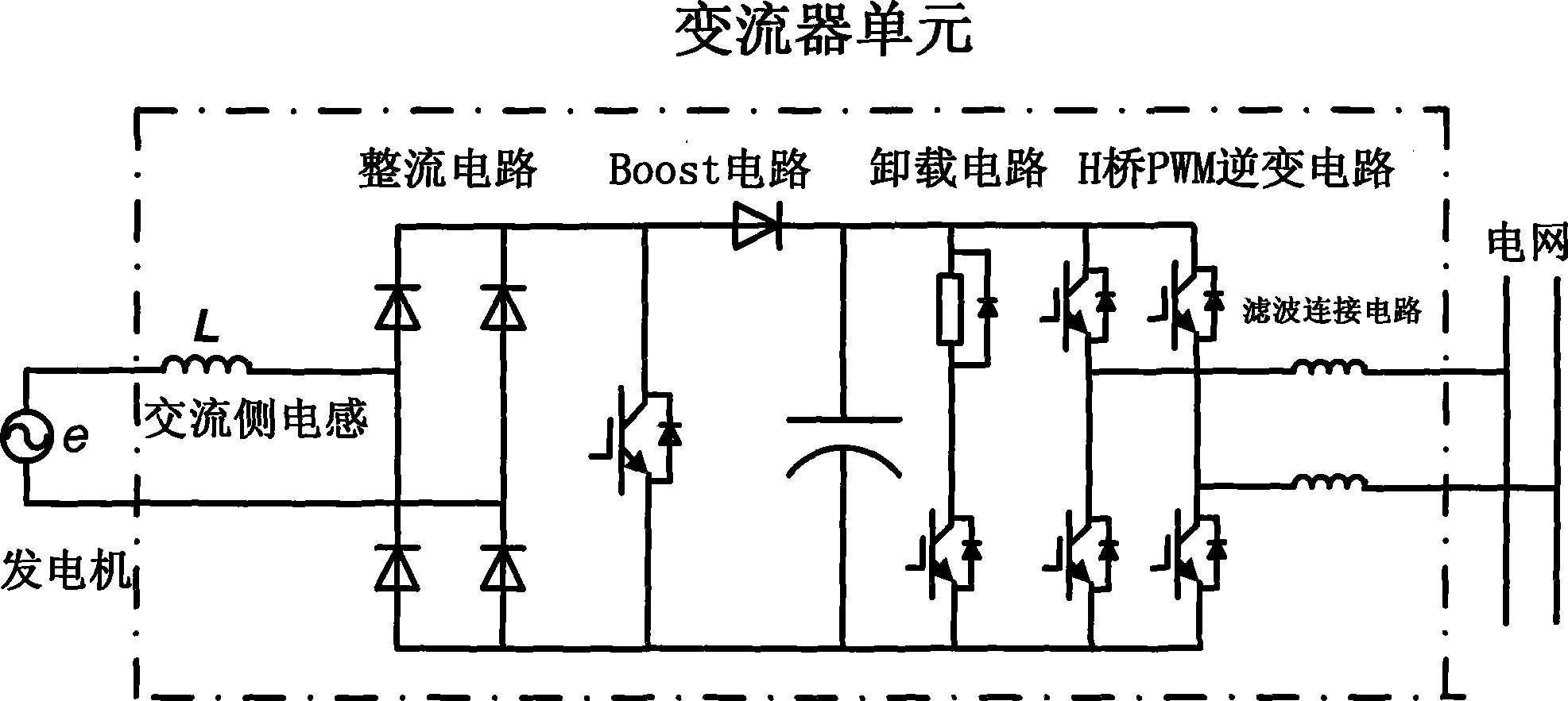
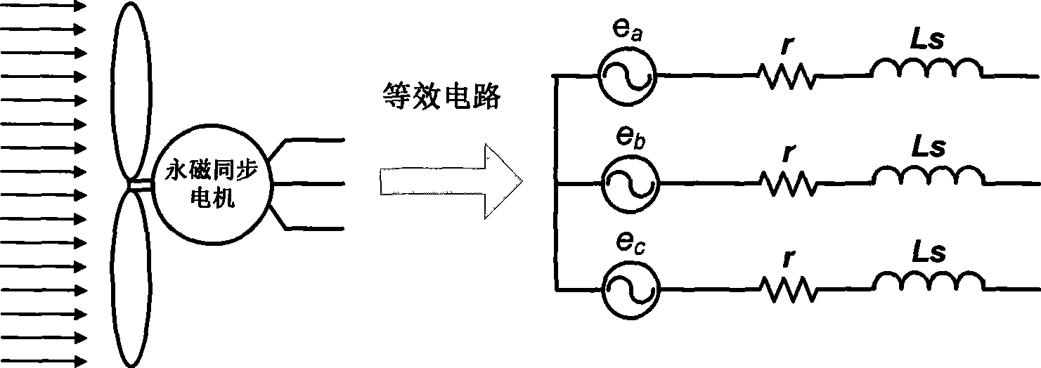
[0046] as attached Figure 11 The direct-drive wind power generation system composed of 20kW converter is shown. The input side of the converter works in diode rectification mode. The wind turbine directly drives the three-phase permanent magnet synchronous generator, and its output terminal is connected to the three-phase diode full bridge Rectifier circuit, the output terminal of the rectifier circuit is connected with the power switching device (IGBT or IGCT, etc.) The AC side of the inverter is connected to the three-phase grid through an LCL filter connection circuit and a transformer. The rated power of the permanent magnet synchronous generator in the system is 20kW, the equivalent inductance of the motor stator winding is 7.5mH, the rectification circuit adopts the three-phase rectification module of Fuji 1600V / 100A, and the boost circuit and inverter circuit adopt Mitsubishi CLA ser...

Embodiment 2

[0049] Embodiment 2: 30kW~500kW direct drive wind power converter (diode rectification mode)

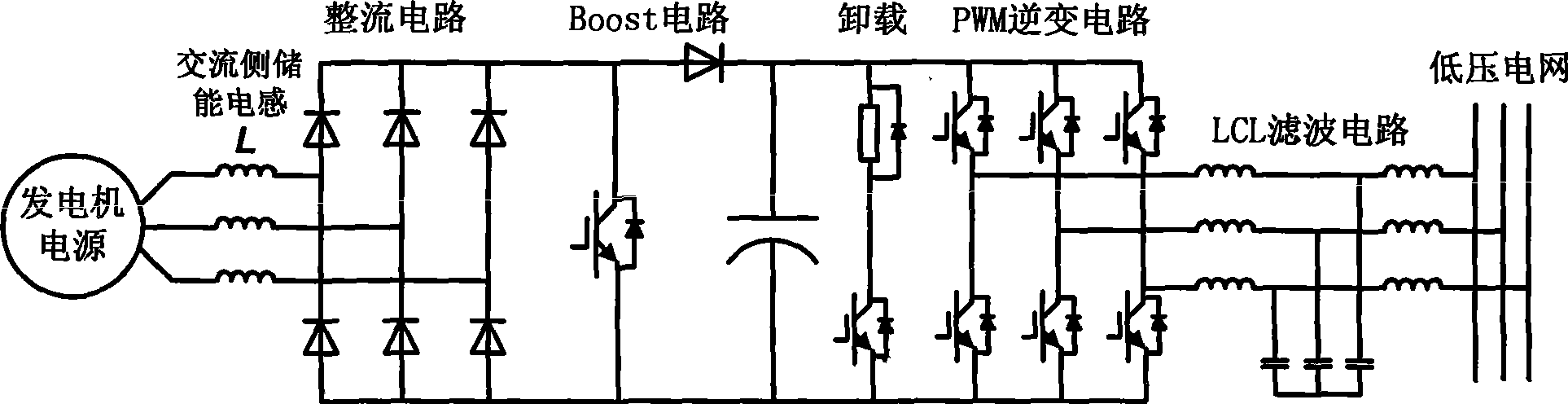
[0050] On the basis of the first embodiment, by selecting large-capacity power electronic devices, the rectification side adopts the attached Figure 5 The multiple structure of the Boost circuit shown in the inverter side adopts the attached Image 6 The parallel structure of the power devices shown can increase the capacity of the converter device, as shown in the attached Figure 12 And attached Figure 13 shown. attached Figure 12 The structure of multiple Boost circuits is adopted on the rectification side; Figure 13 On the basis of multiple Boost circuits on the rectifier side, devices are connected in parallel on the inverter side. After adopting this scheme, the capacity of the converter device can reach 500kW.

Embodiment 3

[0051] Embodiment 3: 1.5MW direct drive wind power converter (diode rectification mode)

[0052] attached Figure 14 And attached Figure 15 Shown is a schematic structural diagram of a 1.5MW direct-drive wind power generation system. attached Figure 14 The medium converter is composed of four units, and each converter unit contains a Boost circuit; the stator winding of the 1.5MW permanent magnet synchronous generator is designed as 12 phases, and every 3 phases are divided into groups and connected to four transformers respectively. input side of the converter unit. Each converter unit includes an independent rectifier circuit, Boost circuit, DC bus capacitor and H-bridge inverter circuit. Each converter unit is in parallel structure, connected together by H-bridge cascading at the output end, and then through The LCL filter connection circuit and transformer are connected to the grid. attached Figure 15 The medium converter is composed of three units, and each conve...


PUM


Abstract

Disclosed are a grid-connected converter device of a direct-drive wind power system and a corresponding power coordination control method. The converter device is composed of basic converter units of a Boost circuit based on ac-side energy storage; the structure sufficiently utilizes the equivalent inductance of a power generator stator winding, avoids an external inductor in traditional dc voltage booster circuit, and reduces power loss and equipment cost. Two converter proposals, including a diode rectification mode and a PWM rectification mode are designed; converter topologies with two capacity grades, including medium and small power converter topology, megawatt grade high power converter topology, and relative extension structures are designed, such as a parallel connection converter and an H bridge cascade structure converter; wherein, the converter with the H bridge cascade structure is applicable to grids with high capacity and high voltage, and can obviously reduce the harmonic content in grid-connected current; meanwhile, the control method performing feedback through three closed loops is designed, so the input power and output power of the converter are balanced instantaneously, the dc bus voltage maintains stable, and the grid-connected current wave is sine.

Description

technical field [0001] The invention relates to the field of energy technology, in particular to the grid-connected converter technology of a direct-drive wind power generating set. Background technique [0002] With the continuous development of renewable energy, the power generation of wind turbines is increasing, and the requirements for reliability and efficiency of wind turbines are also increasing. The existence of gearboxes limits the development of double-fed wind turbines. It is in this case that the direct drive wind power generation system appears. The synchronous generator used in the direct-drive wind power generation system adopts a special design scheme, and its large number of pole pairs enables the generator to still work efficiently when the rotor speed is low; in the direct-drive wind power generation system, the wind turbine Directly coupled with the rotor of the synchronous generator, eliminating the need for a gearbox, improving efficiency, reducing ge...

Claims


Application Information

Patent Timeline
IPC IPC(8): H02M5/44H02M5/458H02J3/38
Inventor 刘建政梅红明
Owner 刘建政
Why Eureka
Try Eureka