Urine Collector

a collection device and collection device technology, applied in the field of health care products, can solve the problems of difficult use of conventional urinary collection devices for urine collection, hardship in urination, and real suffering of patients, and achieve the effects of convenient cleaning, light weight, and thin structur

Active Publication Date: 2018-07-19
SU SOPHIA HAI YUN
View PDF9 Cites 15 Cited by
  • Summary
  • Abstract
  • Description
  • Claims
  • Application Information

AI Technical Summary

Benefits of technology

[0012]Another object of the present invention is to provide a urine collector which is suitable to be used on both the soft and the hard mattress, thereby preventing the urine collector from sinking into the mattress.
[0013]Another object of the present invention is to provide a urine collector which is convenient to be cleaned.
[0014]Another object of the present invention is to provide a urine collector which has a smooth contacting surface, so that the sharp the corner angle is removed and the patients feel comfortable sitting on the urine collector.
[0015]Another object of the present invention is to provide a urine collector, wherein the urine collector is formed in a compact structure and is light in weight, such that the urine collector can be used by the patients for overnight. In other words, health care workers do not need to frequently unload the urine in the urine collector of the present invention.
[0016]Another object of the present invention is to provide a urine collector which has a relatively thinner structure and can discharge urine continuously.
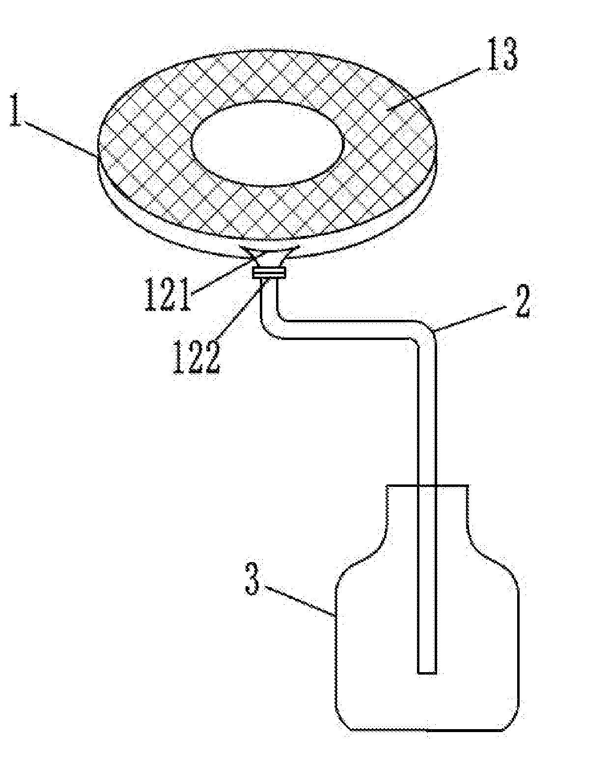
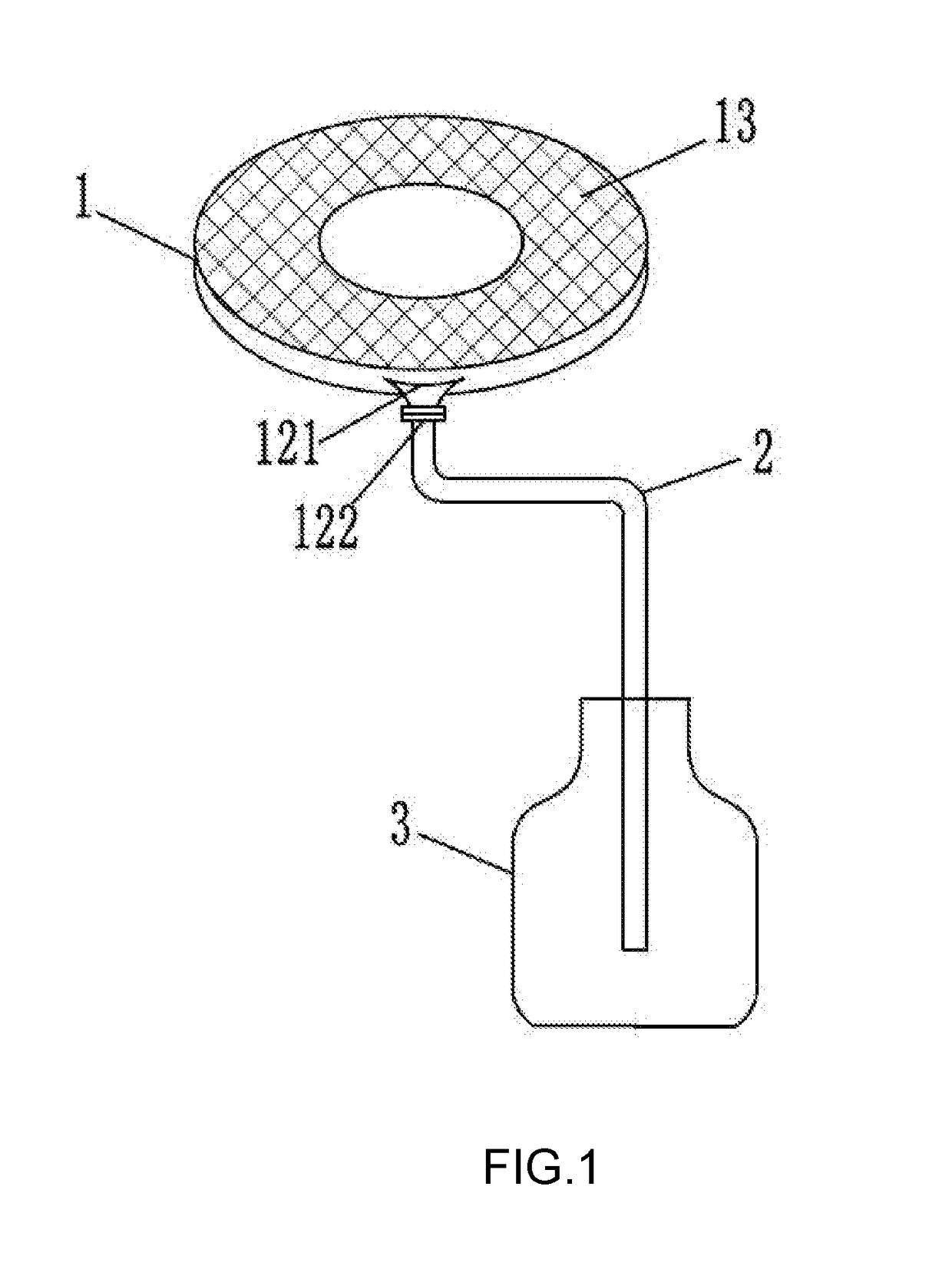
[0017]Another object of the present invention is to provide a urine collector which is adapted to collect urine throughout the hip area but not limiting to the urination portion, so as to prevent leaking out of urine. In addition, a top side a top cover of the collector of the urine collector is inclinedly extended from an outer peripheral edge toward a center, so as to ensure and guide all the urine be collected toward a container through a top opening of the collector to avoid splashing and leakage. Since the collector is not used to store urine being collected but to function as a transition means to continue to guide the container, the collector can be constructed in compact size with a thinner thickness and a lighter weight that enables an overnight usage without the need to replace the collector. Accordingly, to a less severe patient, the patient can place the collector in position by himself or herself and there is no need to have anyone to help for urination. To a more severe patient, it simply needs someone to slight support the hip of the patient to place the collector in position for urination that substantially alleviates suffering to the patient and reduces burden of the care for the patient. For hospitals or senior care facilities, the collector can be directly connected to the sewage drain system that links to a urine collection container for ease of filtration or disinfection treatment, so that the present invention can save a lot of manpower and meet the environmental health requirement.

Problems solved by technology

To a physically-disabled patient, urination is a hardship to the patient or the patient family member or nurse who takes care the patient.
It may require one or two people to assist the patient for each urination and it is really suffering to the patient.
In other words, such conventional urinary collection devices are difficult to use for urine collection and urine always leaks between the contacting surface of the urinary collection device and the body of the patient.
Bed linens and clothing are contaminated due to the urine leakage, so as to cause different health problems such as infection or pressure ulcers.
An improved urine collector for bedridden patients to solve the common problems of the current urine collectors can only cover on the meatus urinarius of the patient, the improved urine collector is difficult to collect all discharging urine from the patients.
As a result, bed linens and clothing are easily to be contaminated by the urine.
In addition, physically-disabled patients with low limb fracture, pelvic fracture, or postpartum are difficult to use the above mentioned urine collectors because they are not powerful enough to retain the urine collector in position.
An improper use of urine collector may cause serious injures due to the excessive movement of the patients.

Method used


Image

  • Urine Collector
  • Urine Collector
  • Urine Collector

Examples


first embodiment

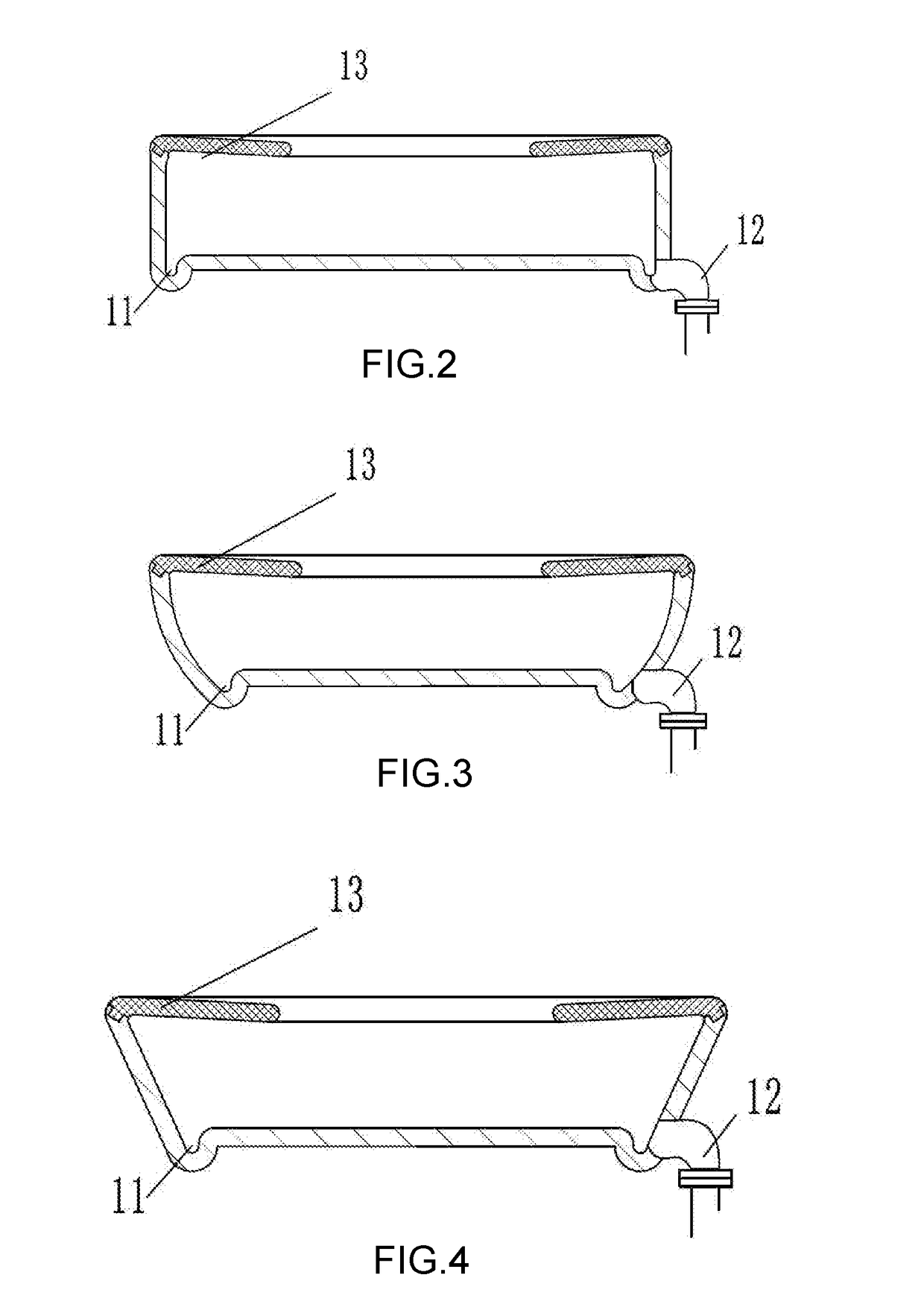
[0067]Accordingly, the outer peripheral edge 21′ of the top cover 20′ is detachably coupled at the surrounding wall 12′ of the collector 10′. Preferably, a coupling slot 111′ is formed at a top edge of the surrounding wall 12′ of the collector 10′, wherein the outer peripheral edge 21′ of the top cover 20′ is detachably coupled at the coupling slot 111′ of the collector 10′. It is worth mentioning that the surrounding wall 12′ of the collector 10′ can be configured to have a vertical wall, an arc-shaped wall, or an inclined wall as mentioned in the

[0068]As shown in FIG. 6, the top side of the top cover 20′ is sloped downwardly from the outer peripheral edge 21′ of the top cover 20′ to the inner peripheral edge 22′ thereof for guiding the urine to flow into the collector 10′. In case the urine is spilled on the top cover 20′, the slanted top side of the top cover 20′ will guide the urine to flow toward the through hole 23′ so as to collect the urine in the collector 10′.

[0069]In addi...

third embodiment

[0091]It is worth mentioning that the urine collector in the third embodiment can be systematic used by the hospitals or the nursing home. For example, the urine collector can be installed in the sickbed and the urine can be guided through the transporting tube 42A to a uniform urine collection pool for unified disposal.

[0092]It is worth mentioning that the urine collector further comprises a urine isolating net 80A detachably attached on the center of the top cover 20A and over the through hole 23A. The urine isolating net 80A is able to isolate the urine and prevent the urine from splashing, thereby keeping cleaning and dry-touch. Preferably, the urine isolating net 80A is made of plastic and is disposable after use.

[0093]As shown in FIG. 10 of the drawings, a urine collector according to an alternative mode of the third embodiment of the present invention is illustrated. The urine collector of this alternative mode has a similar structure with the third embodiment as shown in FIG...

fifth embodiment

[0099]The structure of the urine collector is similar to the structures thereof in the above embodiments. The main improvement is that the urine collector in the fifth embodiment further comprises a bottom supporting base 50C installed on the bottom of the collector 10C.

[0100]Specifically, the bottom supporting base 50C comprises a base plate 54C, a base surrounding wall 51C extended upward from the base plate 54C and has a receiving cavity 53C defined by the base plate 54C and the base surrounding wall 51C. The base surrounding wall 51C has a discharge receiving gap 52C receiving the discharging port 41C of the discharging unit 40C, thereby preventing from affecting the discharging of the urine through the discharging port 41C. The diameter of the bottom supporting base 50C is slightly larger than the diameter of the collector 10C.

[0101]Preferably, the base plate 54C is thin and the height of the base surrounding wall 51C is shorter than the height of the surrounding wall 12C of th...


PUM


Abstract

A urine collector for collecting urine for a user includes a basin which includes a collector including a bottom wall and a surrounding wall upwardly extended therefrom to define a cavity and a top opening, and a top cover supported on the top opening of the collector; and a urine guider provided at the bottom wall of the collector for collecting urine at a peripheral portion thereof for collecting the urine at the urine guider within the cavity of the collector, wherein the bottom wall of the collector further includes an enlarge bottom base defining a circular guiding slot, and an inner concave guiding bottom extended inward and upward from the enlarge bottom base, so that the enlarge bottom base enhances a stabilization of the collector, wherein the urine guider is provided at the inner concave guiding bottom.

Description

CROSS REFERENCE OF RELATED APPLICATION[0001]This is a Continuation-In-Part application that claims the benefit of priority under 35 U.S.C. § 120 to a non-provisional application, application Ser. No. 14 / 673,784, filed Mar. 30, 2015.NOTICE OF COPYRIGHT[0002]A portion of the disclosure of this patent document contains material which is subject to copyright protection. The copyright owner has no objection to any reproduction by anyone of the patent disclosure, as it appears in the United States Patent and Trademark Office patent files or records, but otherwise reserves all copyright rights whatsoever.BACKGROUND OF THE PRESENT INVENTIONField of Invention[0003]The present invention relates to a health care product, and more particularly to a urine collector for special patients who are not easy to move around such as vertebral fracture patients, bone fracture patients, apoplexy patients and obese patients.DESCRIPTION OF RELATED ARTS[0004]The use of a urinary collection device is well kno...

Claims


Application Information

Patent Timeline
Patent Type & Authority Applications(United States)
IPC IPC(8): A61F5/44
CPCA61F5/4405A61F5/455
Inventor SU, SOPHIA HAI YUN
Owner SU SOPHIA HAI YUN
Why Eureka
Try Eureka