Hybrid Electric Motor with Self Aligning Permanent Magnet and Squirrel Cage Rotors

a permanent magnet, hybrid technology, applied in the direction of dynamo-electric machines, magnetic circuit rotating parts, magnetic circuit shapes/forms/construction, etc., can solve the problems of low-power induction motors that are not highly efficient at designed operating speed, permanent magnets that create transient breaking torque, undesirable anomalies, etc., to improve the sequence of inductive startup and efficient synchronous operation

Active Publication Date: 2018-07-26
FINKLE LOUIS J
View PDF4 Cites 7 Cited by
  • Summary
  • Abstract
  • Description
  • Claims
  • Application Information

AI Technical Summary

Benefits of technology

[0011]In accordance with another aspect of the invention, there is provided an inner Squirrel Cage (SC) rotor having angularly spaced apart axially extending slots on an outer surface of the inner SC rotor. The spacing of the slots matching the spacing of permanent magnets in an independently rotating hybrid permanent magnet/squirrel cage (HPMSC) outer rotor. At synchronous speed the slots and permanent magnets cooperate to form salient poles coupling the rotation of the SC inner rotor with the HPMSC outer rotor, eliminating a need for mechanical coupling of the HPMSC outer rotor with the SC inner rotor.
[0012]In accordance with yet another aspect of the invention, there is provided a motor having an improved sequ...

Problems solved by technology

Unfortunately, low power induction motors are not highly efficient at designed operating speed, and are even less efficient under reduced loads because the amount of power consumed by the stator remains constant at such reduced loads.
Unfortunately, the permanent magnets create transient breaking torque and undesirable anomalies until synchronization occur...

Method used


Image

  • Hybrid Electric Motor with Self Aligning Permanent Magnet and Squirrel Cage Rotors
  • Hybrid Electric Motor with Self Aligning Permanent Magnet and Squirrel Cage Rotors
  • Hybrid Electric Motor with Self Aligning Permanent Magnet and Squirrel Cage Rotors

Examples


third embodiment

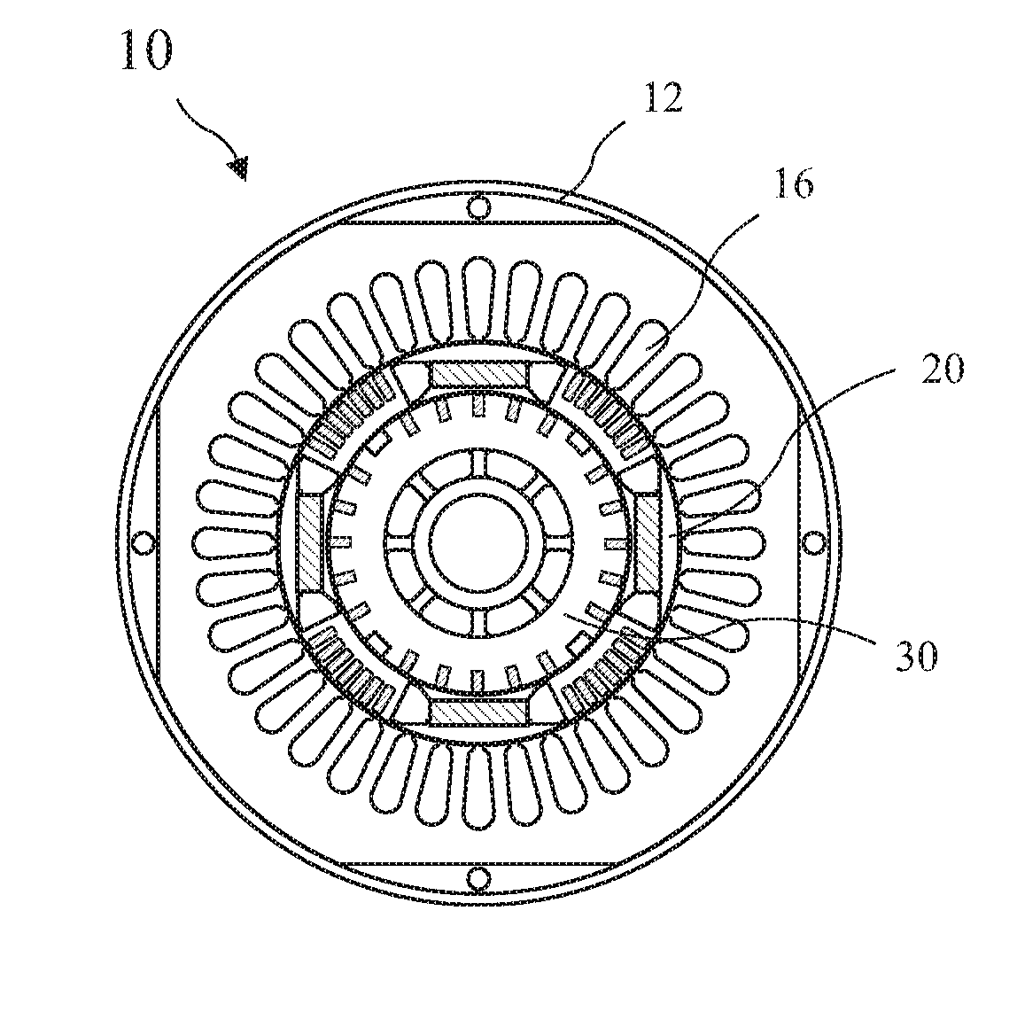
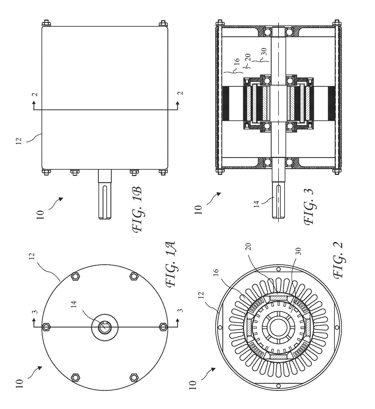
[0105]A cross-sectional view of the electric motor 10b having third embodiment of the independently rotating HPMSC outer rotor 20b and the SC inner rotor 30b fixedly coupled to a motor shaft taken along line 2-2 of FIG. 1B, is shown in FIG. 14 and a cross-sectional view of the electric motor 10b taken along line 3-3 of FIG. 1A, is shown in FIG. 15. The SC inner rotor 30b does not include the slots 34 of the SC inner rotor 30.

second embodiment

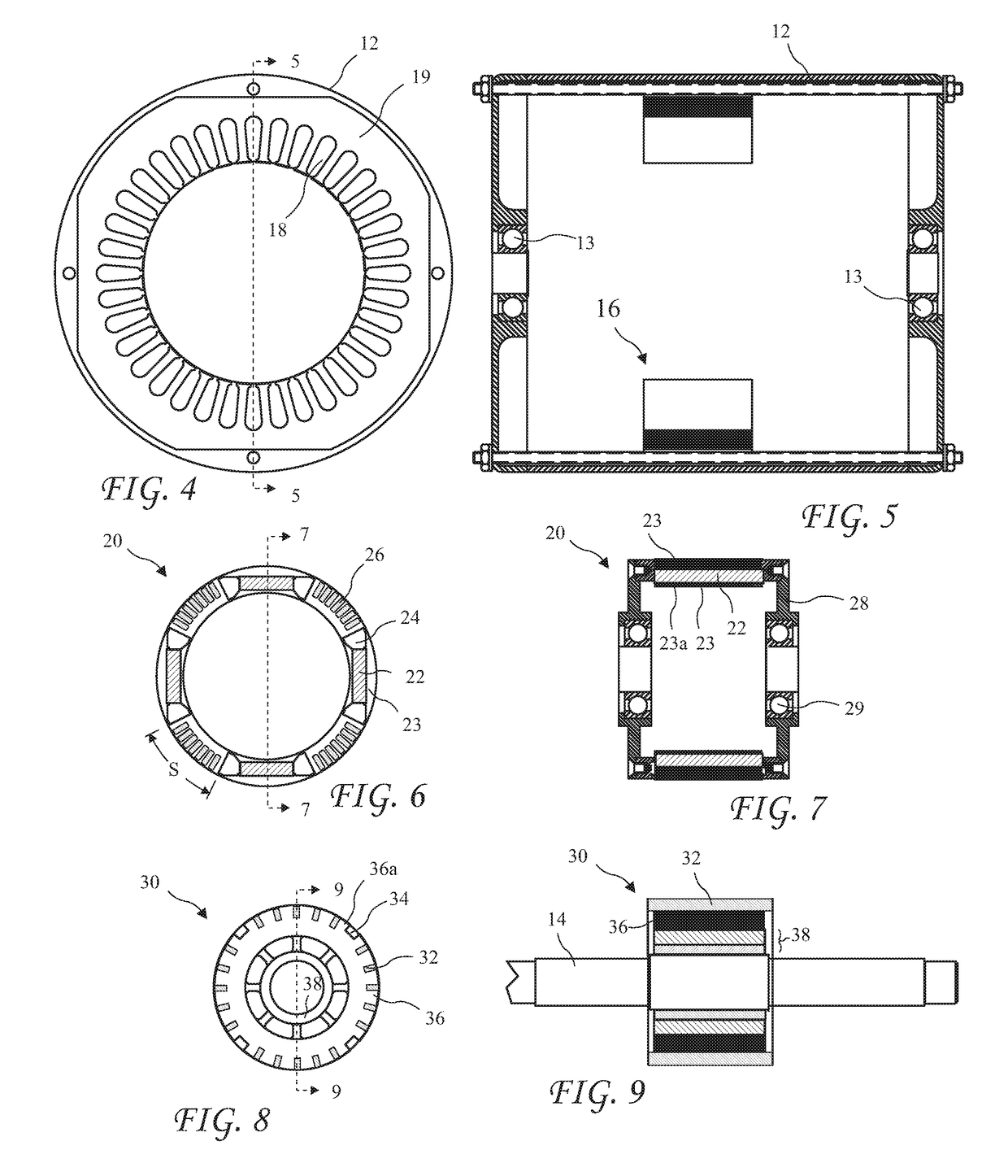
[0106]A cross-sectional view of the independently rotating HPMSC outer rotor 20a taken along line 2-2 of FIG. 1B, is shown in FIG. 16 and a cross-sectional view of the rotor 20a taken along line 17-17 of FIG. 16, is shown in FIG. 17. The HPMSC outer rotor 20a includes four bars 26 between consecutive magnets 22.

[0107]A cross-sectional view of the third embodiment of the independently rotating HPMSC outer rotor 20b taken along line 2-2 of FIG. 1B, is shown in FIG. 18 and a cross-sectional view of the HPMSC outer rotor 20b taken along line 19-19 of FIG. 18, is shown in FIG. 19. The HPMSC outer rotor 20b includes five bars 26 between consecutive magnets 22.

[0108]A cross-sectional view of the second embodiment of the electric motor 10a showing magnetic field lines 40a and 42a at startup taken along line 2-2 of FIG. 1B, is shown in FIG. 20 and a cross-sectional view of the electric motor 10a showing magnetic field lines 52a at synchronous speed taken along line 2-2 of FIG. 1B, is shown i...

first embodiment

[0110]the invention thus discloses a clutch-less hybrid squirrel cage / permanent magnet motor comprising:

[0111]a motor housing;

[0112]a stator fixed to the motor housing and producing a rotating stator magnetic field;

[0113]a motor shaft rotatably connected to the motor housing and extending from at least one end of the motor housing for attachment to a load;

[0114]a hybrid squirrel cage / permanent magnet rotor residing coaxial with the motor shaft and having a first rotor core, a number N of angularly spaced apart permanent magnets embedded in the rotor core, non-ferrous gaps in the rotor core present at ends of each permanent magnet, and first bars embedded in the rotor core, the hybrid squirrel cage / permanent magnet rotor capable of rotating independently of the motor shaft; and

[0115]a squirrel cage rotor residing coaxial with the motor shaft and having a second rotor core, second bars embedded in the second rotor core, and the number N uniformly angularly spaced apart axially running...


PUM


Abstract

A hybrid induction motor includes a fixed stator, an independently rotating outer rotor, and an inner rotor fixed to a motor shaft. The outer rotor is designed to have a low moment of inertia and includes angularly spaced apart first bars and permanent magnets on an inner surface of the outer rotor. The inner rotor includes angularly spaced apart second bars and interior flux barriers aligned with the second bars. The outer rotor is initially accelerated by cooperation of a rotating stator magnetic field with the first bars. As the outer rotor accelerates towards synchronous RPM, a rotating magnetic field of the permanent magnets cooperate with the second bars of the inner rotor to accelerate the inner rotor. At near synchronous speed the rotating stator magnetic field reaches through the outer rotor and into the inner rotor coupling the two rotors for efficient permanent magnet operation.

Description

CROSS-REFERENCE TO RELATED APPLICATIONS[0001]The present application is a Continuation In Part of U.S. patent application Ser. No. 14 / 151,333 filed Jan. 9, 2014, a Continuation In Part of U.S. patent application Ser. No. 14 / 229,673 filed Mar. 28, 2014, and a Continuation In Part of U.S. patent application Ser. No. 15 / 438,023 filed Feb. 21, 2017, which applications is incorporated in its entirety herein by reference.BACKGROUND OF THE INVENTION[0002]The present invention relates to electric motors and in particular to an induction motor having an independently rotating permanent magnet rotor variably coupled to an inductive rotor to reconfigure the motor from asynchronous induction operation at startup to synchronous operation after startup for efficient operation.[0003]A preferred form of electric motors are brushless AC induction motors. The rotors of induction motors include a cage (or squirrel cage resembling a “hamster wheel”) rotating inside a stator. The cage comprises axially ...

Claims


Application Information

Patent Timeline
IPC IPC(8): H02K21/46H02K1/22H02K16/02H02K17/26
CPCH02K21/46H02K1/223H02K16/02H02K17/26H02K1/2706H02K1/2786H02K1/246H02K1/276H02K1/2791H02K17/20
Inventor FINKLE, LOUIS J.
Owner FINKLE LOUIS J
Why Eureka
Try Eureka