Substrate transport device, detection position calibration method and substrate processing apparatus

a technology of substrate processing and transport device, applied in the direction of electrical apparatus, basic electric elements, testing/measurement of semiconductor/solid-state devices, etc., can solve the problem of limiting the highly accurate adjustment of the position of the plurality of detectors, and achieve the effect of high accuracy in the processing of substrates and highly accurate adjustment of positions

Active Publication Date: 2018-08-02
DAINIPPON SCREEN MTG CO LTD
View PDF0 Cites 1 Cited by
  • Summary
  • Abstract
  • Description
  • Claims
  • Application Information

AI Technical Summary

Benefits of technology

[0006]An object of the present invention is to provide a substrate transport device capable of improving transport accuracy of a substrate, a detection position calibration method by which the transport accuracy of the substrate can be improved and a substrate processing apparatus in which the transport accuracy of the substrate can be improved.
[0025]In the substrate processing apparatus, even in the case where there are deviations between the design positions and the actual positions of the plurality of detectors, the substrate can be transported to the predetermined position in the processing unit. Therefore, the transport accuracy of the substrate can be improved. Other features, elements, characteristics, and advantages of the present invention will become more apparent from the following description of preferred embodiments of the present invention with reference to the attached drawings.

Problems solved by technology

However, there is a limit to highly accurate adjustment of positions of the plurality of detectors during manufacture or maintenance of the substrate transport device.

Method used


Image

  • Substrate transport device, detection position calibration method and substrate processing apparatus
  • Substrate transport device, detection position calibration method and substrate processing apparatus
  • Substrate transport device, detection position calibration method and substrate processing apparatus

Examples


first embodiment

(1) Configuration of Substrate Transport Device

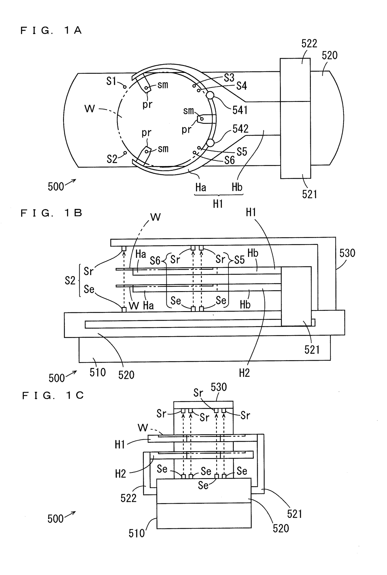
[0042]FIGS. 1A, 1B and 1C are a plan view, a side view and a front view of the substrate transport device 500 according to the first embodiment.

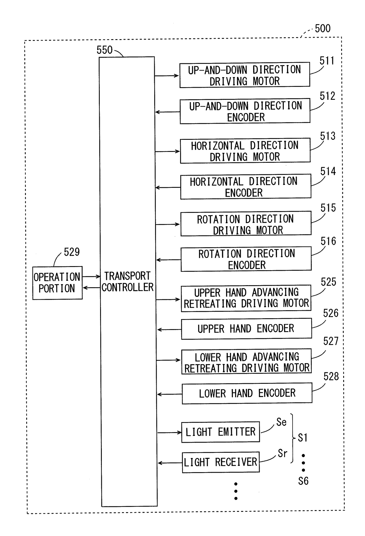
[0043]The substrate transport device 500 of FIG. 1 includes a movement member 510 (FIGS. 1B and 1C), a rotation member 520, two hands H1, H2 and a plurality of detectors S1 to S6 (FIG. 1A). In the present embodiment, the six detectors S1 to S6 are provided. The movement member 510 is configured to be movable in a horizontal direction along a guide rail (not shown).

[0044]The substantially cuboid-shaped rotation member 520 is provided on the movement member 510 to be rotatable about an axis extending in an up-and-down direction. The hands H1, H2 are supported at the rotation member 520 by support members 521, 522, respectively. The hands H1, H2 are configured to be advanceable and retreatable in a longitudinal direction of the rotation member 520. In the present embodiment, the hand H2 is located ...

second embodiment

(7) Detection Position Calibrating Operation in Second Embodiment

[0082]A substrate transport device 500 according to the second embodiment is different from the substrate transport device 500 according to the first embodiment in that deviations in the X axis direction of the detectors S1 to S6 are corrected in the detection position calibrating operation. A configuration of the entire substrate transport device 500 and a configuration of a transport controller 550 according to the second embodiment are similar to the configurations shown in FIGS. 1A, 1B, 1C, 4 and 5.

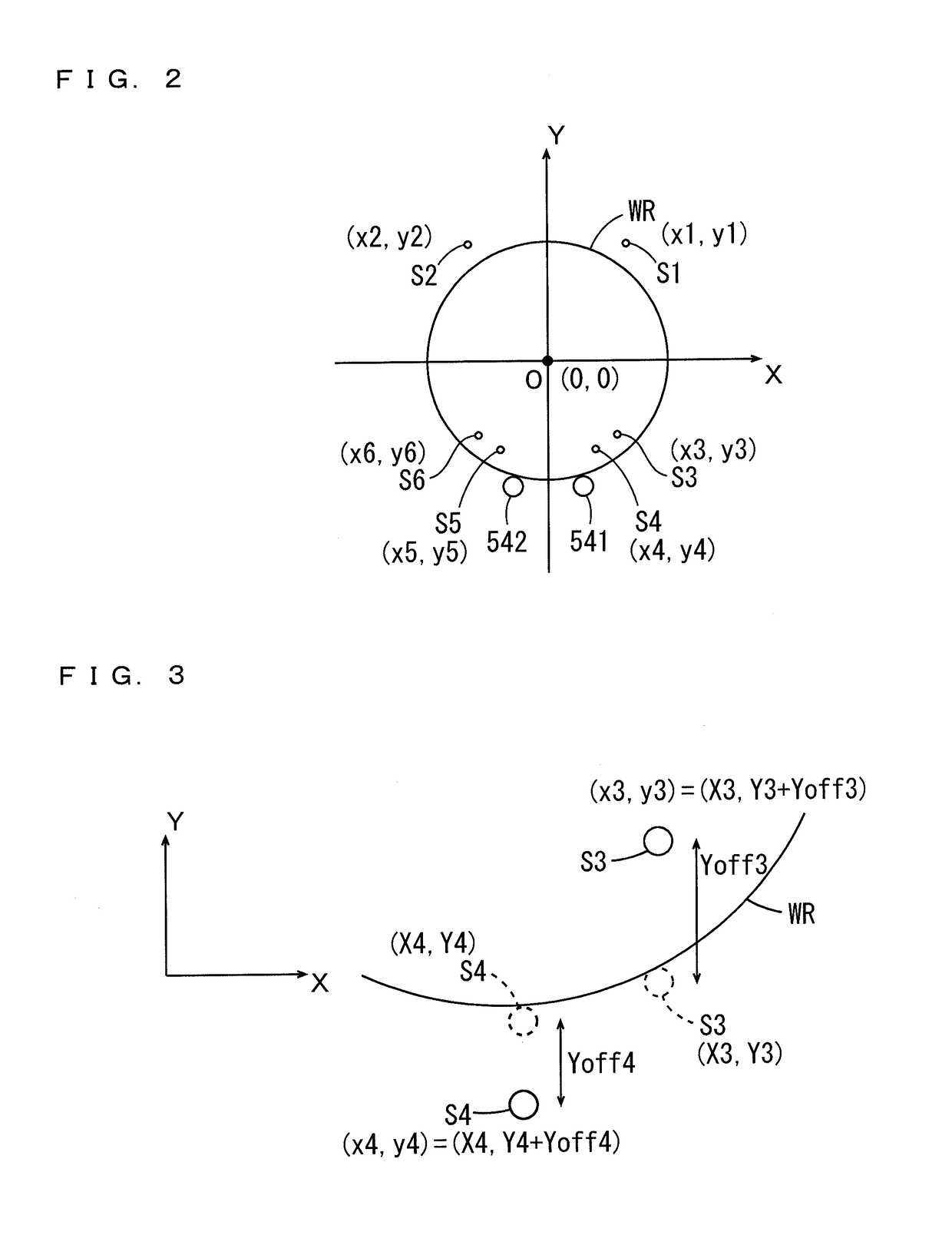
[0083]FIGS. 7A and 7B are diagrams showing a positional relationship between a plurality of detectors S1 to S6 and a substrate in the second embodiment. In the following description, the reference substrate WR is held by the hand H1 (see FIG. 1A). The invention also applies to the case where the reference substrate WR is held by the hand H2 (see FIG. 1B). In FIG. 7, the hand H1 is not shown.

[0084]Similarly to the first e...


PUM


Abstract

During a detection position calibrating operation and a substrate transport operation, a detection coordinate calculator calculates detection coordinates of an outer periphery of a reference substrate or a substrate placed at a reference position on a hand. During the detection position calibrating operation, an offset calculator calculates offsets of a plurality of detectors based on detection coordinates and design coordinates. During the substrate transport operation, a detection coordinate corrector corrects the detection coordinates based on the offsets of the plurality of detectors, and a coordinate information corrector corrects coordinate information based on the corrected detection coordinates. A movement controller controls an up-and-down direction driving motor, a horizontal direction driving motor and a rotation direction driving motor and controls an upper hand advancing retreating driving motor and a lower hand advancing retreating driving motor, such that the substrate is transported from a reception position to a placement position based on the corrected coordinate information.

Description

BACKGROUND OF THE INVENTIONField of the Invention[0001]The present invention relates to a substrate transport device that transports a substrate, a detection position calibration method for calibrating a detection position of the substrate in the substrate transport device, and a substrate processing apparatus.Description of Related Art[0002]Substrate processing apparatuses are used to subject substrates such as semiconductor substrates, substrates for liquid crystal display devices, substrates for plasma displays, substrates for optical discs, substrates for magnetic discs, substrates for magneto-optical discs, substrates for photomasks and other substrates to various types of processing.[0003]Generally, in such a substrate processing apparatus, processing is successively performed on one substrate in a plurality of processing units. Therefore, a transport mechanism (substrate transport device) that transports the substrate among the plurality of processing units is provided in the...

Claims


Application Information

Patent Timeline
Patent Type & Authority Applications(United States)
IPC IPC(8): H01L21/687H01L21/67
CPCH01L21/68707H01L21/67259H01L21/6719H01L21/677H01L21/681H01L22/12H01L21/67766H01L21/67781H01L21/68H01L21/67742
Inventor KUWAHARA, JOJI
Owner DAINIPPON SCREEN MTG CO LTD
Why Eureka
Try Eureka