Automatic gain control (AGC) circuit, despreading circuit, and method for reproducing reception data

a gain control and circuit technology, applied in the direction of amplification control, transmission, electric devices, etc., can solve the problems of degrading reception performance and reducing the resolution of output signals, and achieve the effects of high output signal resolution, small quantization error, and high resolution

Active Publication Date: 2018-08-02
LAPIS SEMICON CO LTD
View PDF18 Cites 1 Cited by
  • Summary
  • Abstract
  • Description
  • Claims
  • Application Information

AI Technical Summary

Benefits of technology

[0005]To solve the above problem, an object of the present invention is to provide an automatic gain control (AGC) circuit having a small quantization error and a high output signal resolution, and a despreading circuit and a method for reproducing reception data that provide high reception performance.
[0009]According to the present invention, it is possible to provide an automatic gain control (AGC) circuit having a small quantization error and a high output signal resolution. The AGC circuit can perform a bit width conversion with a high resolution, even in a signal non-receiving state. It is also possible to provide a despreading circuit and a method for reproducing reception data that prevent degradation in reception performance.

Problems solved by technology

In the above-described automatic gain control (AGC) circuits, the reduced bit width of the demodulator causes a reduction in the resolution of an output signal, thus degrading reception performance.

Method used


Image

  • Automatic gain control (AGC) circuit, despreading circuit, and method for reproducing reception data
  • Automatic gain control (AGC) circuit, despreading circuit, and method for reproducing reception data
  • Automatic gain control (AGC) circuit, despreading circuit, and method for reproducing reception data

Examples


first embodiment

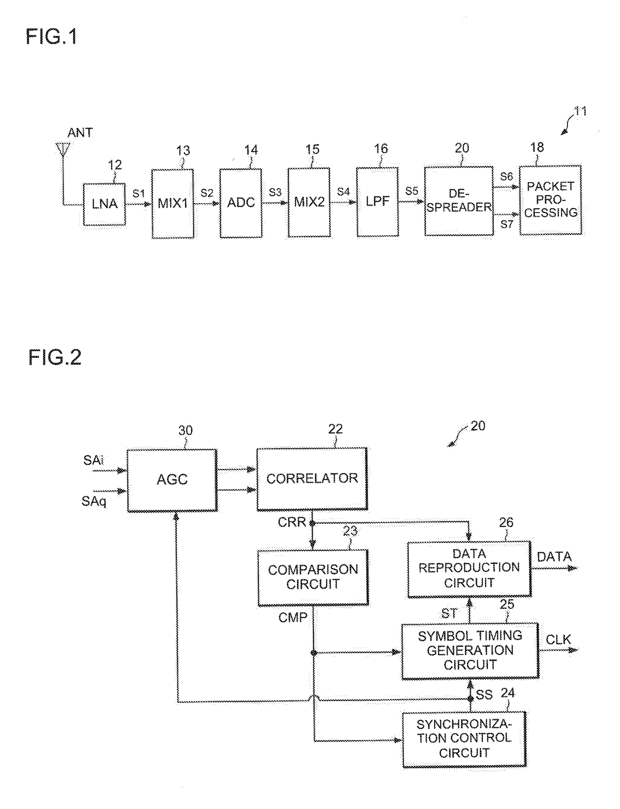
[0023]FIG. 1 is a block diagram showing an example of a configuration of a receiver 11 using a spread spectrum (SS) technology. The spread spectrum receiver 11 receives a transmission signal the spectrum of which is spread by, for example, direct sequence (DS) spreading.

[0024]A reception signal received by an antenna ANT of the spread spectrum receiver 11 is input to a low-noise amplifier circuit (LNA) 12. The LNA 12 amplifies the reception signal, and a mixer circuit (MIX1) 13 converts the frequency of the amplified reception signal S1 from a radio frequency (RF) into an intermediate frequency (IF).

[0025]A first analog-to-digital converter (ADC circuit) 14 applies an analog-to-digital conversion to the IF signal S2 after the frequency conversion, to digitize the IF signal S2. In the spread spectrum receiver 11, each signal may be processed as a signal constituting of an in-phase signal (I signal), a quadrature signal (Q signal), and the like.

[0026]The IF signal S3 digitized by the ...

second embodiment

[0052]FIG. 7 is a block diagram showing an example of a configuration of an AGC circuit 40 according to a second embodiment. The difference between the AGC circuit 40 and the AGC circuit 30 according to the first embodiment is that the AGC circuit 40 includes first and second resistors 36A and 36B and a selector 41. The other components of the AGC circuit 40 are the same as those of the AGC circuit 30 according to the first embodiment.

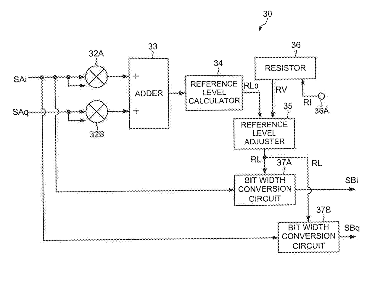
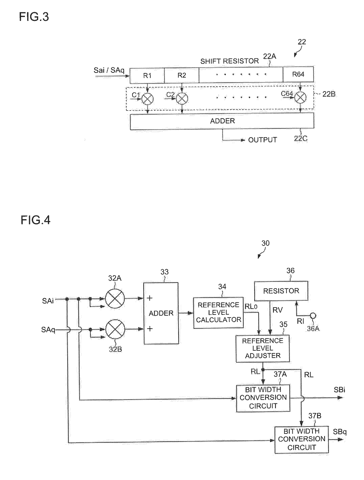
[0053]As in the case of the first embodiment, the AGC circuit 40 converts m-bit width signals SAi and SAq input thereto into n-bit width signals SBi and SBq (m>n), respectively, and outputs the signals SBi and SBq. In the following description, the signals SAi and SAq each have a 10-bit width (m=10), and the signals SBi and SBq each have a 3-bit width. However, the bit widths are not limited thereto, and can take any number as long as m>n is satisfied.

[0054]The first and second resistors 36A and 36B store first and second adjustment values (or setting ...


PUM


Abstract

An automatic gain control circuit includes a reference level calculator that calculates a reference level on the basis of the amplitude of a reception signal; a resistor that stores an adjustment value for the reference level; a reference level adjuster that adjusts the reference level on the basis of the adjustment value stored in the resistor, and generates an adjusted reference level; and a bit width conversion circuit that performs a bit width conversion to reduce the bit width of the reception signal, on the basis of the adjusted reference level.

Description

BACKGROUND OF THE INVENTION1. Field of the Invention[0001]The present invention relates to an automatic gain control (AGC) circuit used in a spread spectrum receiver, a despreading circuit having such an AGC circuit, and a method for reproducing reception data.2. Description of the Related Art[0002]A spread spectrum scheme is known as a communication scheme having high resistance to noise and interference. Spread spectrum receivers include an automatic gain control (AGC) circuit that controls the signal levels of input signals to correlators, with respect to varying reception levels.[0003]For example, Patent Literature 1 (Japanese Patent Application Laid-Open No. H11-088232) discloses an automatic gain control (AGC) circuit and a spread spectrum receiver that can retrieve n-bit data from m-bit data (m>n) output from a correlator, on the basis of an effective number of bits, in order to reduce the bit width of a demodulator. Patent Literature 2 (Japanese Patent Application Laid-Op...

Claims


Application Information

Patent Timeline
Patent Type & Authority Applications(United States)
IPC IPC(8): H03G3/30H04B1/16H04B1/69
CPCH03G3/3042H04B1/16H04B1/69H03G3/30H04B1/123H04B1/707H03G3/3052H03G3/3078H04B1/7073
Inventor HAFUKA, TAKAMITSU
Owner LAPIS SEMICON CO LTD
Why Eureka
Try Eureka