Eureka AIR delivers breakthrough ideas for toughest innovation challenges, trusted by R&D personnel around the world.

Radially Expandable Annulus Reinforcement Prosthesis

Active Publication Date: 2018-08-09
SPICA MEDICAL TECH LLC
View PDF9 Cites 4 Cited by
  • Summary
  • Abstract
  • Description
  • Claims
  • Application Information

AI Technical Summary

Benefits of technology

The present invention provides an intervertebral annular reinforcement implant with a delivery and deployment system and an attachment system. The prosthetic implant is made of elastomeric materials, which can expand and contract within the spine to repair a damaged spine. The delivery and deployment system can minimize damage to the surrounding tissue and accurately place the implant. The temporary high-pressure balloon can help to distract the adjacent vertebrae and the inflated balloon helps to stabilize the spine. The method of disengagement from the inflation cannula is atraumatic and ensures proper sealing of the balloon. Overall, the invention provides a safe and effective method for repairing damaged spines.

Problems solved by technology

In general, prior art prostheses have limitations in their compliance properties, compactness, and foldability.
Another disadvantage of presently available intradiscal devices is that they lack radial and longitudinal compliance, and are too rigid or stiff.
A notable challenge encountered in prior art designs of prostheses intended for intradiscal implantation is to maintain compliance, elasticity, collapsibility, and flexibility of the prosthesis.
Furthermore, grafts utilized lacked resilience and durability.
These latter structures are not capable of withstanding the applied compression and torsional loads and they gradually deteriorate.
Thus, the layers can move independently and this obviates the problem of compliance mismatch between the two layers of the implant.

Method used


Image

  • Radially Expandable Annulus Reinforcement Prosthesis
  • Radially Expandable Annulus Reinforcement Prosthesis
  • Radially Expandable Annulus Reinforcement Prosthesis

Examples


Embodiment Construction

[0068]Turning now to the Figures, reference numbers are used to designate corresponding elements in the Figures. The Figures depict selected embodiments. Although the present invention will be described with reference to preferred embodiments, those skilled in the art will recognize that changes may be made in form and detail without departing from the scope and spirit of the invention. Examples of construction, materials, dimensions, and manufacturing process are provided. It is intended that the following detailed specification be regarded as illustrative rather than limiting, and it is the appended claims, including all equivalents thereof, which are intended to define the scope of the invention.

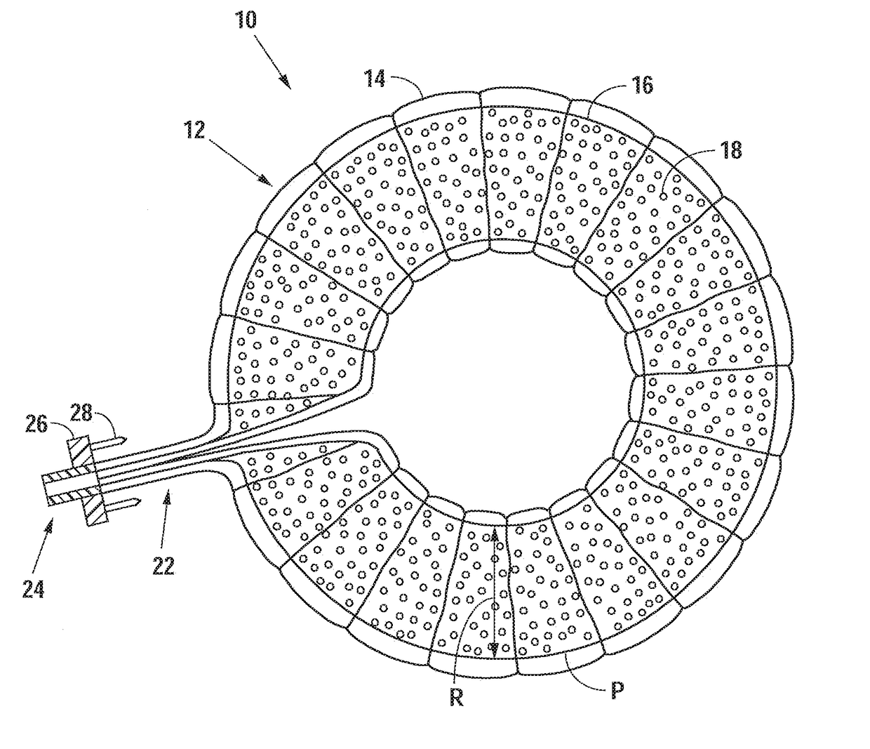
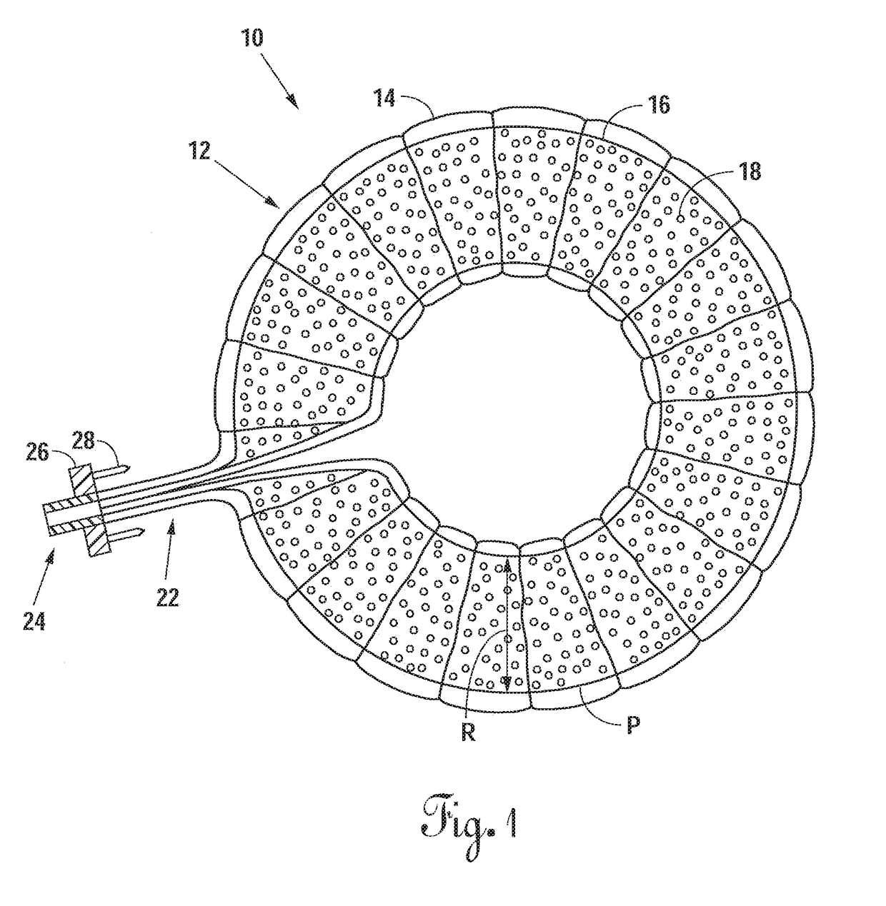
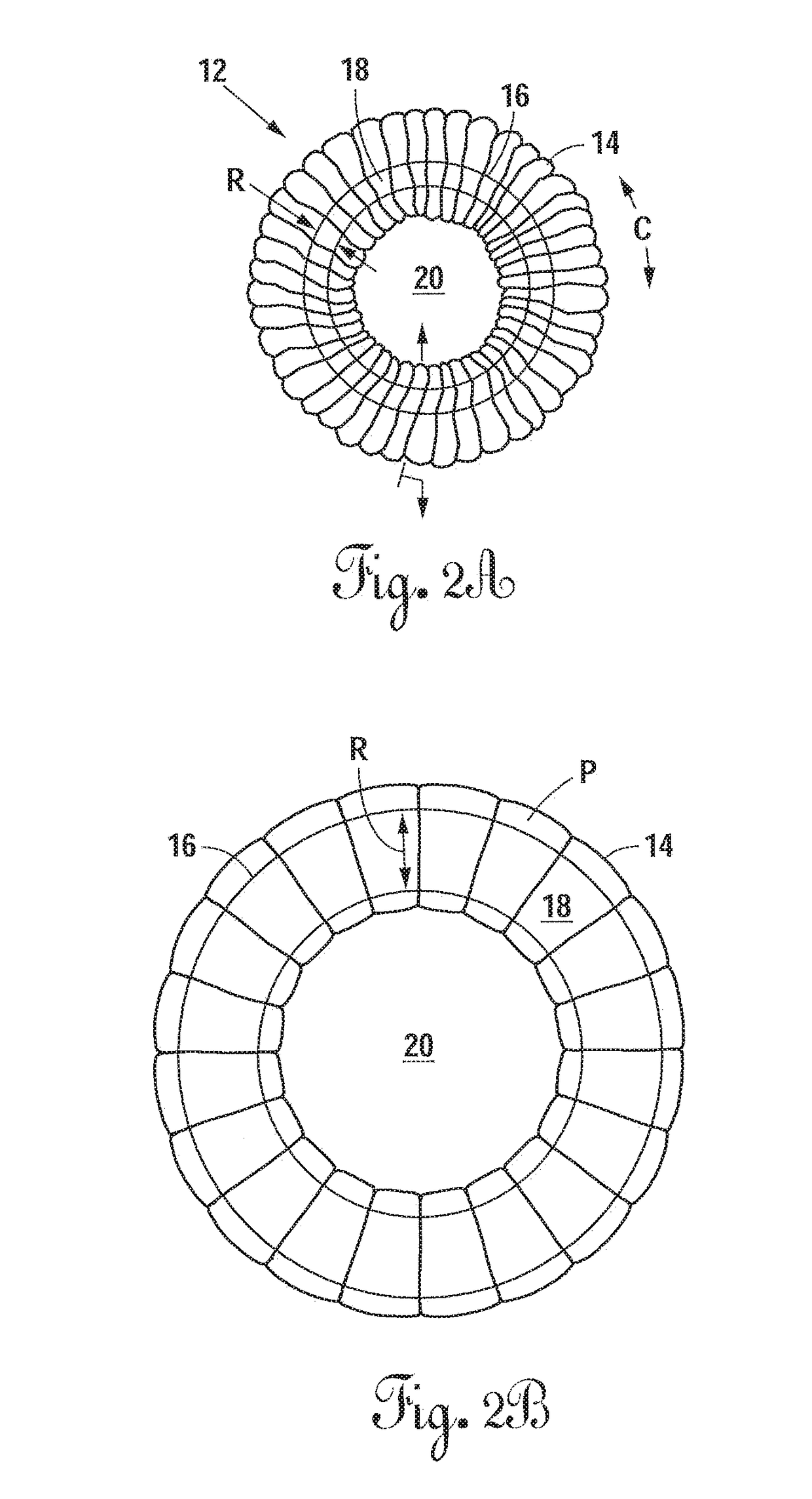
[0069]Referring now to FIG. 1, there is shown an embodiment of an intervertebral elastomeric device 10. The device 10 comprises an annular component 12 which comprises an annular balloon 16 formed in the shape of an annular membrane, and a textile supporting sleeve 14 positioned about the...


PUM


Abstract

An intervertebral implantation system for restoring disc height and vertebral alignment, while allowing dynamic mobility and stabilization of the vertebral segment, and minimally invasive methods of implanting the same. The implantation system includes an annular reinforcement implant, including an elastomeric balloon inserted into the hollow or interior of a tubular sleeve, and secured only at a first and second neck portions to a securement element coupled to an attachment fixture, forming an annular structure attached to the outer margin of the annulus fibrosus. When the prosthetic implant is in a contracted state the tubular sleeve is redundant and undulated, forming folds, gathered loosely around the circumference of the inner balloon. Upon pressurized inflation with in-situ curable polymer, the elastomeric balloon elongates and expands circumferentially, and the tubular sleeve stretches and unfolds, constraining further expansion and elongation of the elastomeric balloon. The attachment fixture is configured to provide secure attachment to the outer margin of the annulus fibrosus. A temporary, high pressure vertebral distraction balloon is utilized to aid in vertebral distraction during a surgical procedure to implant the annular reinforcement implant.

Description

BACKGROUND1. Field of the Invention[0001]The present invention generally relates to an annular expandable intervertebral disc prosthesis. More particularly, the present invention relates to a prosthetic graft structure which can be inflated in-situ to form an implant useful for supporting a damaged or torn annulus fibrosus, and for correction of deformity associated with adult degenerative lumbar scoliosis (ADLS) and degenerative disc disease (DDD).2. Background[0002]Tubular prostheses are commonly used in various vascular grafting applications. Implantable tubular endoprostheses such as stent-grafts and other similar devices are well known in the art for the treatment of various bodily lumens, such as the gastrointestinal system, the airway, and other applications in the body. The tubular configuration and design of such prostheses is desirable because these prostheses have characteristics which attempt to resemble the body lumen which it is supporting.[0003]Many devices have been ...

Claims


Application Information

Patent Timeline
IPC IPC(8): A61F2/44A61F2/46A61F2/30
CPCA61F2/442A61F2/4611A61F2/30767A61F2/30907A61F2002/4627A61F2002/4435A61F2002/302A61F2002/30069A61F2002/30589A61F2002/30583A61F2002/30841A61F2002/30919A61F2002/4495A61F2/30965A61F2002/30586A61F2002/444A61F2002/4629
Inventor HIBRI, NADI S.
Owner SPICA MEDICAL TECH LLC
Why Eureka
Eureka Blog
Learn More