Angular contact ball bearing, and ball screw device using same

Inactive Publication Date: 2018-08-09
NTN CORP
View PDF2 Cites 4 Cited by
  • Summary
  • Abstract
  • Description
  • Claims
  • Application Information

AI Technical Summary

Benefits of technology

[0006]When an angular contact ball bearing shown in FIG. 16 is used to support a ball screw used mainly to apply linear motion force, it is necessary to increase the diameter Da of each ball 3 to increase the load capacity of the angular contact ball bearing, in order to prolong the life of the angular contact ball bearing. In addition,

Problems solved by technology

During rapid acceleration/deceleration rotation, great force acts on the pillar portions 5b due to delay or advance of the balls, and thus the pillar portions 5b may be damaged if the pillar portions 5b are thin.
Under the above circumstances, a problem is to, in an angular contact ball bearing that bears a large thrust load, allow

Method used


Image

  • Angular contact ball bearing, and ball screw device using same
  • Angular contact ball bearing, and ball screw device using same
  • Angular contact ball bearing, and ball screw device using same

Examples


Example

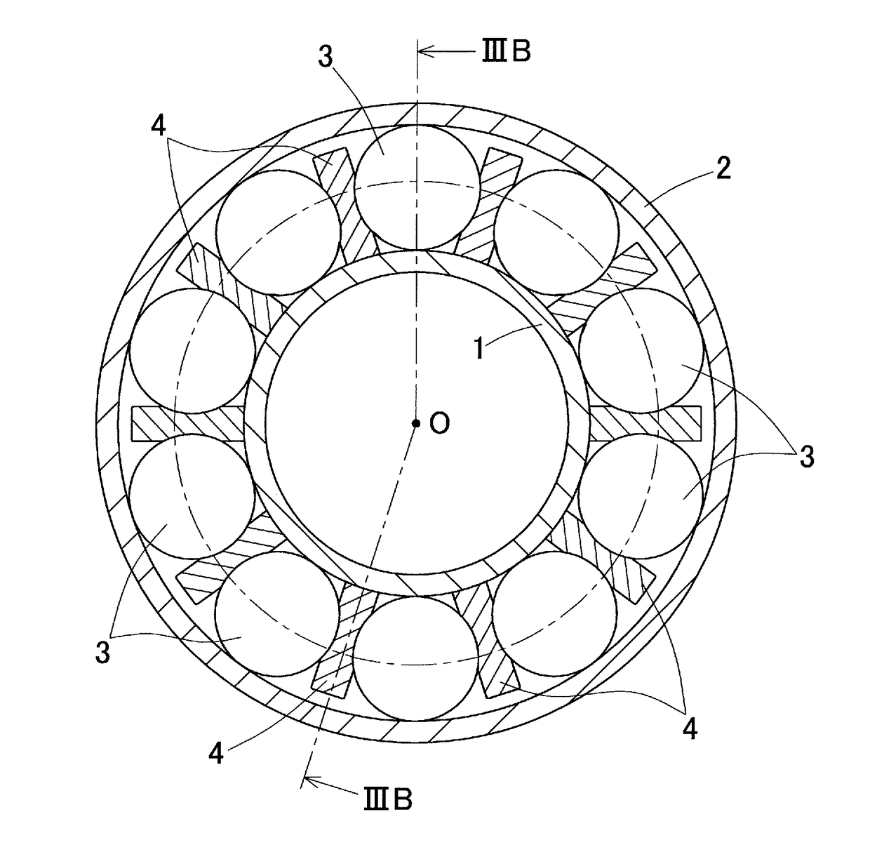
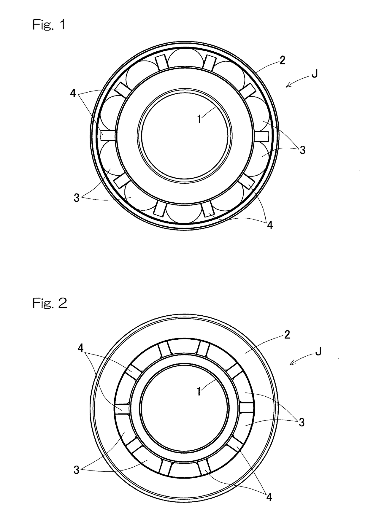
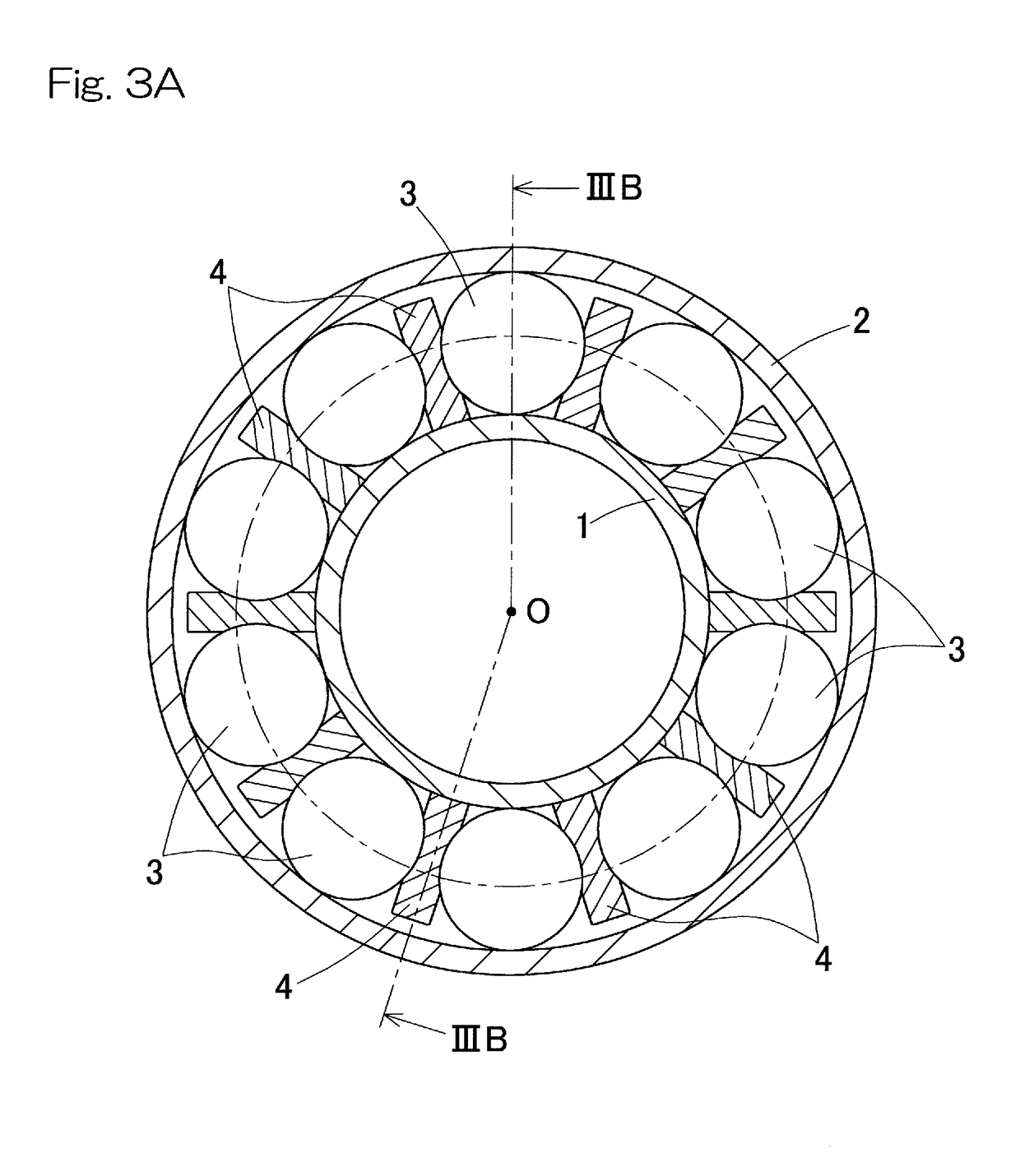
[0047]Embodiments of the present invention will be described with reference to the drawings. FIG. 1 is a front view of an angular contact ball bearing according to an embodiment of the present invention; FIG. 2 is a back view of the angular contact ball bearing; FIG. 3A is a cutaway front view of the angular contact ball bearing; FIG. 3B is a IIIB-O-IIIB cross-sectional view of FIG. 3A; and FIG. 4 is a partially enlarged view of FIG. 3B.

[0048]As shown in FIG. 1 and FIG. 2, the angular contact ball bearing J includes an inner ring 1 having an outer peripheral surface formed with an inner ring raceway groove 1a (FIG. 3B), an outer ring 2 having an inner peripheral surface formed with an outer ring raceway groove 2a (FIG. 3B), and a plurality of balls rollably interposed between the inner ring raceway groove la and the outer ring raceway groove 2a. The plurality of balls 3 are retained by a plurality of separator retainers 4 that are interposed between the adjacent balls 3 and that are...


PUM


Abstract

Provided is an angular contact ball bearing that can have a load capacity increased by increasing the diameter of each ball and that is suitably used mainly to bear a thrust load. In the angular contact ball bearing, a plurality of balls are rollably interposed between an inner ring raceway groove formed on an outer peripheral surface of an inner ring and an outer ring raceway groove formed on an inner peripheral surface of an outer ring. The plurality of balls are retained by a plurality of separator retainers that are interposed between the adjacent balls and that are spaced apart from each other. A contact angle θ of each ball is within a range of 45° to 65°.

Description

CROSS REFERENCE TO THE RELATED APPLICATION[0001]This application is a continuation application, under 35 U.S.C. § 111(a), of international application No. PCT / JP2016 / 079464, filed Oct. 4, 2016, which claims priority to Japanese patent application No. 2015-197525, filed Oct. 5, 2015, and Japanese patent application No. 2016-189478, filed Sep. 28, 2016, the disclosure of which are incorporated by reference in their entirety into this application.BACKGROUND OF THE INVENTIONField of the Invention[0002]The present invention relates to an angular contact ball bearing used to support a ball screw of an injection molding machine, or the like, and a ball screw device using the angular contact ball bearing.Description of Related Art[0003]An injection molding machine is provided with a feed mechanism that causes a resin material extrusion screw to advance / retract, or a feed mechanism that clamps a mold. These feed mechanisms have been recently electrified instead of a conventional hydraulic ty...

Claims


Application Information

Patent Timeline
IPC IPC(8): F16C19/16F16C33/38
CPCF16C19/163F16C33/3887F16H25/24F16C33/3706F16C2240/70F16C2240/34F16C31/04F16C19/16F16C19/20F16C33/58F16C33/37
Inventor TANIMURA, HIROKI
Owner NTN CORP
Why Eureka
Try Eureka