Supercharge Your Innovation With Domain-Expert AI Agents!

System, method, and apparatus for peak shaving and load shaping using power storage with variable power generation

a technology of power storage and power generation, applied in the field of energy management systems, methods and equipment, can solve the problems of inability to reliably operate the energy storage device, the energy demand of a load over time may experience spikes and dips, and the variable energy source may not be reliable, so as to achieve cost saving and cost-effective effects

Active Publication Date: 2018-08-09
BATTELLE ENERGY ALLIANCE LLC
View PDF5 Cites 21 Cited by
  • Summary
  • Abstract
  • Description
  • Claims
  • Application Information

AI Technical Summary

Benefits of technology

The patent text describes advanced algorithms for managing peak power needs and load shapes in different levels of electrical systems. The techniques can be implemented using software and microcontrollers for nanogrids and microgrids, respectively. The technology can reduce the need for peaking power generation and help manage grid congestion, resulting in cost savings for both consumers and electric utilities.

Problems solved by technology

However, some variable energy sources provide intermittent and unpredictable energy generation, and the energy demands of a load over time may experience spikes and dips.
If the energy demand is misaligned to energy generation, then a variable energy source may not be reliable.
Operation of the energy storage device is limited by the availability of energy from the variable energy source.
Some conventional energy management systems include scheduling capability that seeks to forecast variable energy generation and demand at a load, however, forecasts may suffer from large errors (for example, due to weather patterns) or many small errors that aggregate to a net cost.
Conventional energy distribution and management systems may have other drawbacks and deficiencies.

Method used


Image

  • System, method, and apparatus for peak shaving and load shaping using power storage with variable power generation
  • System, method, and apparatus for peak shaving and load shaping using power storage with variable power generation
  • System, method, and apparatus for peak shaving and load shaping using power storage with variable power generation

Examples


Embodiment Construction

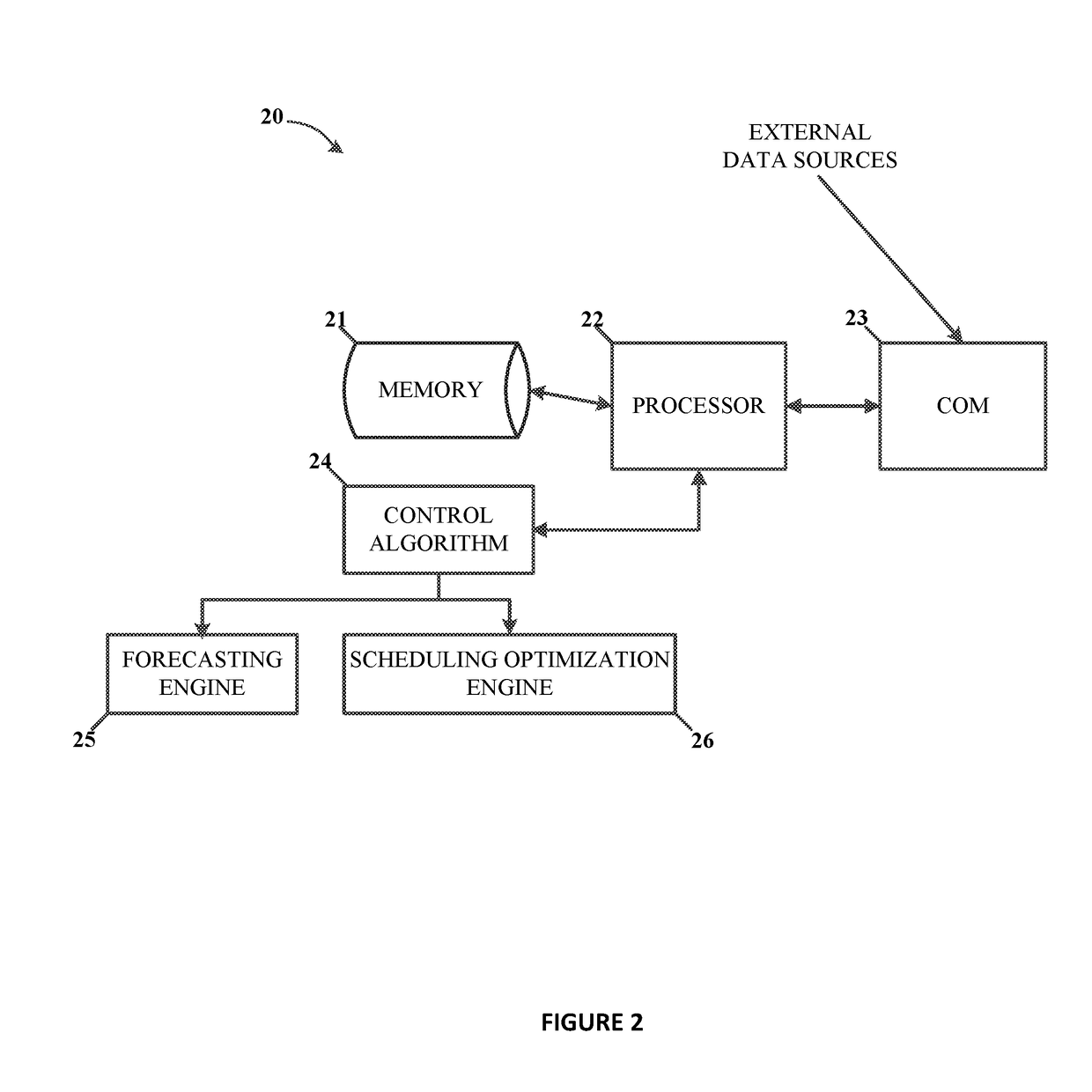
[0025]Various embodiments may include elements described as implemented in a “computer” or a “computer system.” Here, the terms “computer” and “computer system” are to be understood to include at least one non-transitory computer readable memory and at least one processing unit. In general, the memory will store, at one time or another, at least portions of an executable program code, and the processor(s) will execute one or more of the instructions included in that executable program code. It will be appreciated that the term “executable program code” and the term “software” mean substantially the same thing for the purposes of this description. It is not necessary to the practice of the various embodiments described herein that the memory and the processor be physically located in the same place. That is to say, it is foreseen that the processor and the memory might be distributed among physical pieces of equipment or even in geographically distinct locations.

[0026]The processing ...


PUM


Abstract

Systems, methods and apparatuses are provided for reducing peak energy demand and to smooth intermittent energy profiles from onsite variable energy sources and loads. Some embodiments use system level and device level analysis and optimization to adaptively adjust the operation of a behind the meter energy storage (BMES) to smooth out energy generation variabilities and follow a reference load signal, including at short time resolutions.

Description

CROSS-REFERENCE TO RELATED APPLICATION[0001]This application claims the benefit under 35 U.S.C. § 119(e) of U.S. Provisional Patent Application Ser. No. 62 / 456,418, filed Feb. 8, 2017, the disclosure of which is hereby incorporated herein in its entirety by this reference.STATEMENT REGARDING FEDERALLY SPONSORED RESEARCH OR DEVELOPMENT[0002]The invention was made with government support under Contract No. DE-AC07-05-ID14517, awarded by the United States Department of Energy. The government has certain rights in this invention.TECHNICAL FIELD[0003]Embodiments of the present disclosure relate generally to systems, methods, and apparatuses for energy management. Some embodiments relate to techniques for using power storage to optimize supply of power to a load by variable power sources.BACKGROUND[0004]Variable energy sources, such as photovoltaics (e.g., solar power), wind-turbines, thermoelectric systems, etc., may be used for onsite energy generation, that is, energy generation local ...

Claims


Application Information

Patent Timeline
Patent Type & Authority Applications(United States)
IPC IPC(8): H02J3/28H02J13/00G05B15/02
CPCH02J3/28H02J13/0006G05B15/02H02J2003/003H02J3/003H02J13/00007H02J2203/20H02J2300/20H02J3/381H02J13/00016Y04S10/14Y04S40/121Y04S10/50Y04S40/124Y04S10/123Y02E40/70H02J2300/22Y04S20/12Y02B90/20G05B2219/2639H02J3/388H02J3/00
Inventor BHATTARAI, BISHNU P.MYERS, KURT S.
Owner BATTELLE ENERGY ALLIANCE LLC
Features
  • R&D
  • Intellectual Property
  • Life Sciences
  • Materials
  • Tech Scout
  • Unparalleled Data Quality
  • Higher Quality Content
  • 60% Fewer Hallucinations
Learn More