System, method, and device for forming an array of emulsions

a technology of arrays and emulsions, applied in the field of systems, methods, and devices for forming arrays of emulsions, can solve the problems of less user-friendly devices, bulky devices and costly manufactures, and small device users, and achieve the effect of facilitating bonding of sealing members

Active Publication Date: 2018-08-16
BIO RAD LAB INC
View PDF4 Cites 5 Cited by
  • Summary
  • Abstract
  • Description
  • Claims
  • Application Information

AI Technical Summary

Benefits of technology

[0006]The present disclosure provides systems, methods, and devices for forming an array of emulsions. An exemplary device comprises a frame and at least one or a plurality of separate microfluidic modules mounted to the frame and each configured to form an array of emulsions. In some embodiments, each module may be mounted by snap-fit attachment. The device also may include the same sealing member bonded to a top side of each

Problems solved by technology

However, increasing the number of emulsions in the array, to meet the demand for higher sample throughput, presents numerous engineering challenges.
For example, increasing the size of the array without changing its density can make the device bulky and costly to manufacture.
On the other hand, designing a

Method used


Image

  • System, method, and device for forming an array of emulsions
  • System, method, and device for forming an array of emulsions
  • System, method, and device for forming an array of emulsions

Examples


example 1

Cartridge with Frame and Microfluidic Modules

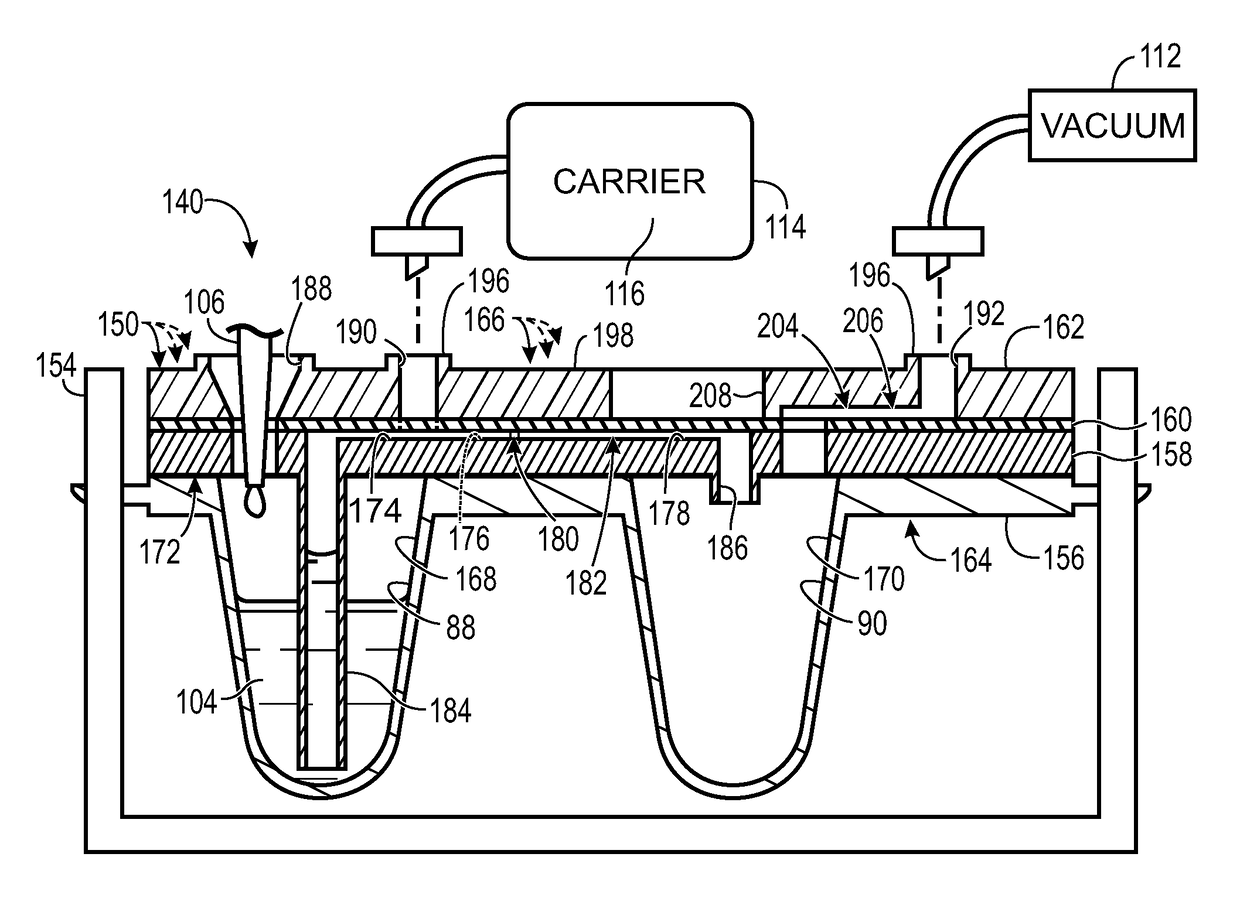
[0096]This section describes further exemplary aspects of microfluidic device 140 of Section I, as embodied by a microfluidic cartridge 300 (interchangeably called a microfluidic device) having a non-fluidic frame that holds microfluidic modules 150; see FIGS. 7-32. Selected structures and features of cartridge 300 that correspond to those described above for microfluidic device 140 have been assigned the same reference numbers as in device 140.

[0097]FIGS. 7-10 show various views of cartridge 300 without (FIGS. 7, 8, and 10) and with (FIG. 9) a sealing member 210 that may hermetically seal the cartridge. The cartridge includes a frame 154 and a plurality of microfluidic modules 150 mounted to the frame. The modules may be substantially identical to one another, and may be mounted to the frame by the manufacturer or the user. Once mounted, the modules may or may not be configured to be removable by the user. The modules may be placed into ...

example 2

Cartridge with Fluidic Frame

[0127]This section describes an exemplary microfluidic cartridge 400 (interchangeably called a microfluidic device) having a frame 402 providing fluidic features for emulsion formation; see FIGS. 33-39. Structures and features of cartridge 400 that correspond to those described above for microfluidic device 140 of Section I and / or cartridge 300 of Example 1 have been assigned the same reference numbers as in device 140 or cartridge 300.

[0128]Cartridge 400 has a plurality of microfluidic modules 404 bonded to frame 402 in a fluid-tight seal. Modules 404 are constructed generally as described above for modules 150 in Example 1, except that guide / port layer 162 of each module is omitted. The guide / port layer is replaced by a vacuum manifold layer 406 and a guide / port layer 408 that are shared among modules 404. Vacuum manifold layer 406 is bonded to a top side of capping layer 160 of each module 404, and guide / port layer 408 is bonded to a top side of manifo...

example 3

Cartridge with Onboard Carrier Reservoir

[0134]This section describes an exemplary microfluidic cartridge 500 (interchangeably called a microfluidic device) having a frame 502 providing fluidic features for emulsion formation, including an onboard reservoir 504 for carrier fluid 116; see FIGS. 40-42. Structures and features of cartridge 500 that correspond to those described above for microfluidic device 140, cartridge 300, and / or cartridge 400 have been assigned the same references numbers as in those devices.

[0135]Cartridge 500 has a structure shared generally with cartridge 400, including modules 404 bonded in a fluid-tight seal to an underside of a platform 506 of frame 502. (Only one module 404 is shown in FIG. 40 to simplify the presentation.) Platform 506 forms a guide / port layer 508 of the cartridge, which has the vacuum manifold 204 of manifold layer 406 of cartridge 400 formed integrally by platform 506, rather than as a separate layer. Platform 506 defines, for each module...


PUM

PropertyMeasurementUnit
Pressureaaaaaaaaaa

Abstract

Systems, methods, and devices for forming an array of emulsions. An exemplary device comprises a frame and at least one or a plurality of separate microfluidic modules mounted to the frame and each configured to form an array of emulsions. In some embodiments, each module may be mounted by snap-fit attachment. The device also may include the same sealing member bonded to a top side of each module and hermetically sealing each of the modules. Another exemplary microfluidic device for forming an array of emulsions comprises a stack of layers bonded together. The stack may comprise a port layer forming a plurality of ports. Each port may have a top rim formed by a protrusion that encircles the central axis of the port. The rims may be coplanar with one another to facilitate bonding of a sealing member to each rim.

Description

CROSS-REFERENCE TO PRIORITY APPLICATION[0001]This application is based upon and claims the benefit under 35 U.S.C. § 119(e) of U.S. Provisional Patent Application Ser. No. 62 / 458,429, filed Feb. 13, 2017, which is incorporated herein by reference in its entirety for all purposes.CROSS-REFERENCES TO OTHER MATERIALS[0002]This application incorporates herein by reference in their entirety for all purposes the following: U.S. Patent Application Publication No. 2010 / 0173394 A1, published Jul. 8, 2010; and U.S. Patent Application Publication No. 2014 / 0378348 A1, published Dec. 25, 2014.INTRODUCTION[0003]Various powerful approaches for analyzing a fluid sample begin by forming an emulsion with the sample. In the emulsion, the sample is a dispersed phase of droplets each encapsulated by an immiscible continuous phase. With a biological sample, the droplets are typically aqueous droplets surrounded by an immiscible carrier liquid comprising oil.[0004]A biological sample can be analyzed for t...

Claims


Application Information

Patent Timeline
IPC IPC(8): B01L3/00G01N1/38B01F3/08B01F13/10
CPCB01L3/502784B01L3/502715G01N1/38B01F3/0811B01F13/1072B01L2200/028B01L2200/0673B01L2200/0689B01L2200/0684B01L2400/049B01L2200/12B01F2215/0037B01L9/527B01L2200/027B01F23/4105B01F33/85B01F2101/23
Inventor CAULEY, TREYDZENITIS, JOHNHOBBS, STEVESCHIAFFINO, STEFANO
Owner BIO RAD LAB INC
Why Eureka
Try Eureka