Eureka AIR delivers breakthrough ideas for toughest innovation challenges, trusted by R&D personnel around the world.

A pulse-separated axial turbine stage with radial-axial inlet guide vanes

Inactive Publication Date: 2018-08-16
BORG WARNER INC
View PDF11 Cites 5 Cited by
  • Summary
  • Abstract
  • Description
  • Claims
  • Application Information

AI Technical Summary

Benefits of technology

The present invention avoids the cost and expense of designing and producing a conventional turbine housing with an inwardly spiraling volute. It simplifies the design and manufacture of turbine housings for receiving radial entry runners with no or only some inclination, which reduces weight and flow inefficiencies. Thus, the technical effect of the invention is to provide a more economical and efficient turbine housing design.

Problems solved by technology

Disadvantageously, the radial flow turbine wheel backwall adds to the weight of the turbine wheel, and this increase in inertia decreases the responsiveness of the turbine wheel.
However, conventional axial turbines generally lack the ability to perform well at higher expansion ratios, such as are typically needed to harness the pulsing energy of the exhaust of an internal combustion engine.
This poorly guided non-uniform flow may create high energy losses, reduced aerodynamic efficiencies, and increased mechanical or vibrational stresses on the turbine during operation due to flow misalignment (high incidence) with the blades 2 of the turbine at wide operating conditions.
Also, the axial turbine stage shown in Lotterman et al. is a high reaction stage, which may lead to supersonic flows with higher aerodynamic losses (passage and secondary flows) in blade passages, as compared to low reaction stages at similar turbine stage loading conditions.
This high blade count increases the cost of the turbine wheel.

Method used


Image

  • A pulse-separated axial turbine stage with radial-axial inlet guide vanes
  • A pulse-separated axial turbine stage with radial-axial inlet guide vanes
  • A pulse-separated axial turbine stage with radial-axial inlet guide vanes

Examples


Embodiment Construction

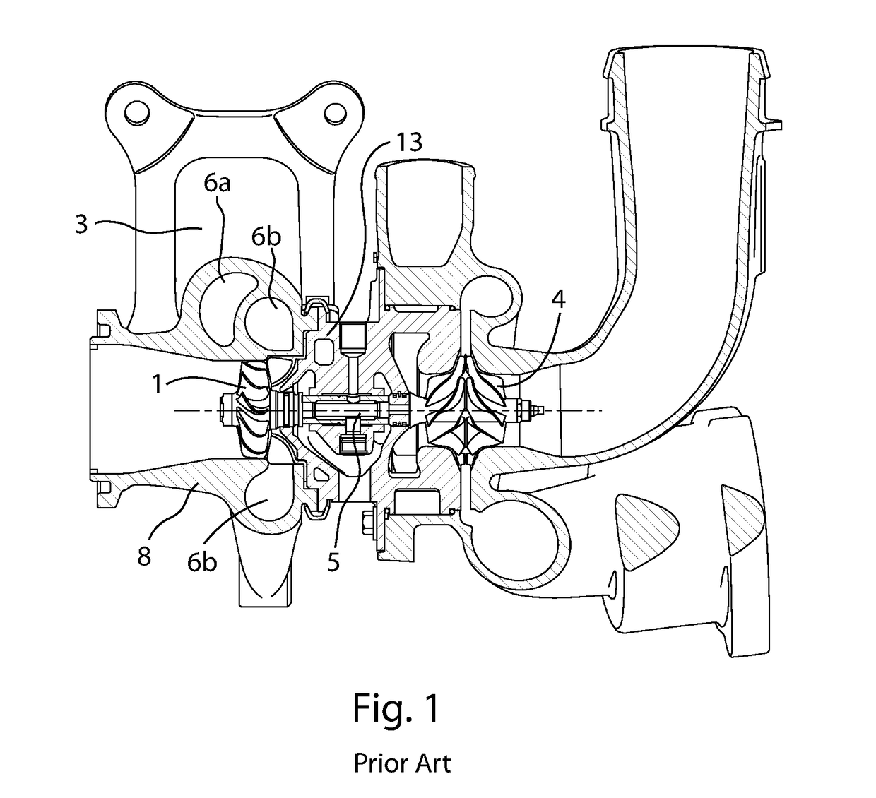
[0026]The inventive turbocharger may be driven by exhaust from a four-stroke diesel engine, or may be any other type of combustion engine such as, for example, a two or four-stroke gasoline or gaseous fuel-powered engine. The engine may be three cylinders, multiple of three cylinders (e.g., two banks of three cylinders), or multiples of two cylinders (two, four, six or eight cylinders) or may include a greater or lesser number of cylinders. The cylinders may be arranged in an in-line configuration, in an opposing-piston configuration, in a V-configuration (i.e., a configuration having first and second banks or rows of cylinders) or in another configuration. The turbocharger may be arranged on one side of the engine, or may be nested between two banks of cylinders. For a six cylinder engine, there may be two turbochargers, e.g., one on each side of the engine.

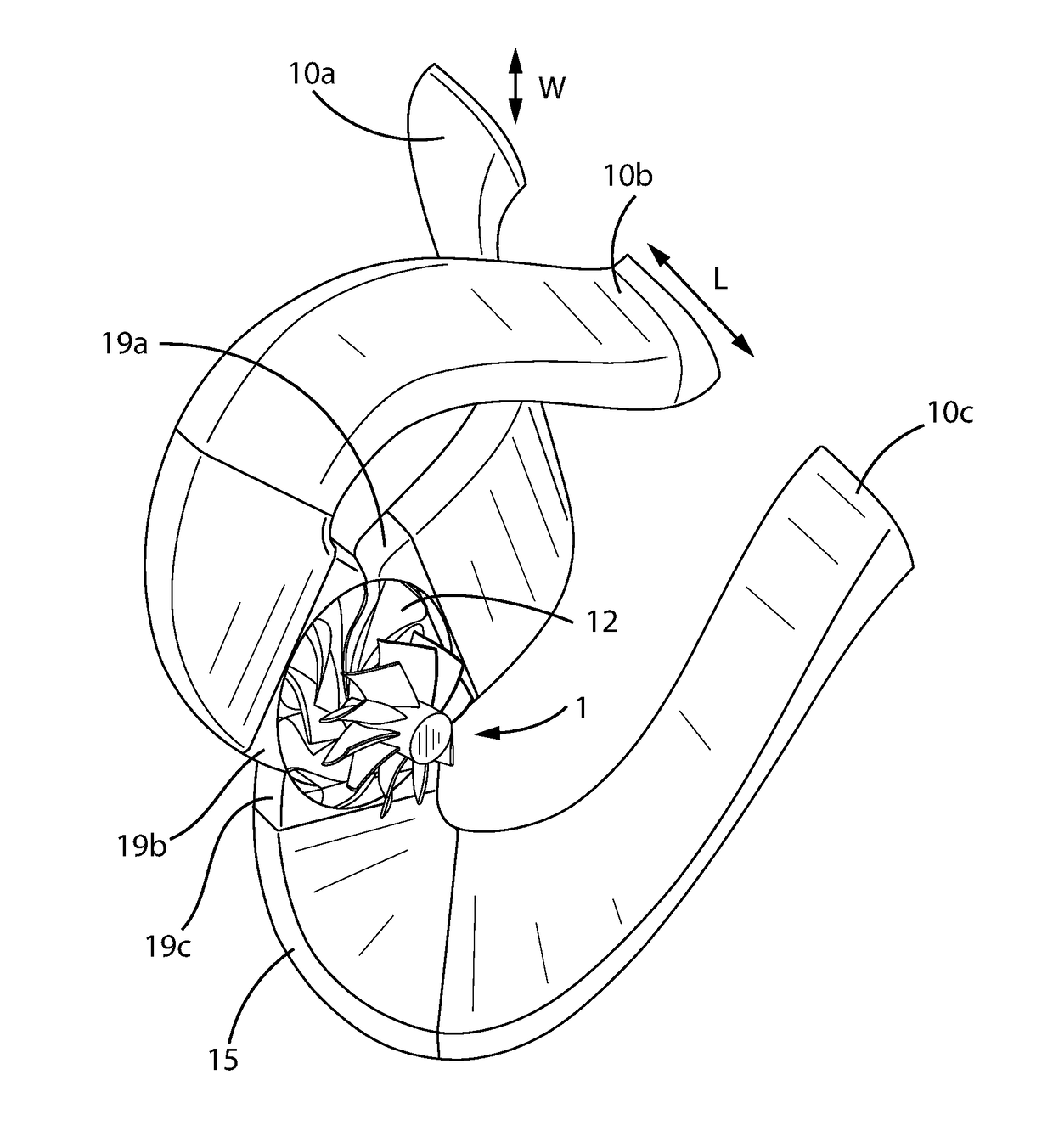
[0027]An exhaust system includes runners 19a, 19b, 19c which direct combustion exhaust from the engine to the exhaust gas turb...


PUM


Abstract

A turbocharger with at least one axial turbine stage. Separate circumferential sections of the turbine are fed by separate exhaust system runners. The turbine is designed to harness pulse energy. Corresponding engine having cylinders comprising such a turbocharger.

Description

BACKGROUND OF THE INVENTIONField of the Invention[0001]The invention concerns a turbocharger with at least one axial turbine stage. Separate circumferential sections of the turbine are fed by separate exhaust system runners, The turbine is designed to harness pulse energy.Description of the Related Art[0002]The turbine of a turbocharger is designed to extract energy from a high pressure and high temperature exhaust gas stream and therewith drive a compressor. There are two main turbine designs: radial flow, in which exhaust gases are directed radially against turbine blades, and axial flow, in which exhaust gasses are directed through a turbine wheel in a generally axial direction.[0003]Radial turbines have been preferred in passenger car and commercial diesel applications because the efficiency of small radial-flow turbines is higher than comparable-size axial flow turbines. The exhaust gas stream flows into a circumferential volute in the turbine housing, which forms a narrowing s...

Claims


Application Information

Patent Timeline
IPC IPC(8): F01D17/16F02B37/24
CPCF01D17/162F02B37/24F05D2220/40F05D2250/51F01D25/24F02B37/00Y02T10/12
Inventor KARSTADT, SASCHABIESINGER, THOMASKROEGER, GEORGSILLER, ULRICH
Owner BORG WARNER INC
Why Eureka
Eureka Blog
Learn More