Swallow tail airfoil

Active Publication Date: 2018-08-23
NEDERLANDSE ORG VOOR TOEGEPAST-NATUURWETENSCHAPPELIJK ONDERZOEK (TNO)
View PDF17 Cites 8 Cited by
  • Summary
  • Abstract
  • Description
  • Claims
  • Application Information

AI Technical Summary

Benefits of technology

[0006]The present invention seeks to provide an improved design of the airfoil shape of a wing body, such as the rotor blade of a wind turbine.
[0007]According to the present invention, an aerodynamic element according to the preamble defined above is provided, wherein the aerodynamic element further comprises an exten

Problems solved by technology

However, all of these types of solutions introduce more complexity in the airfoil.
As a consequence, there is an increase in the cost of development and/or production in order to implement such solutions.
Also, there is a co

Method used


Image

  • Swallow tail airfoil
  • Swallow tail airfoil
  • Swallow tail airfoil

Examples


Example

[0016]The root region of a wind turbine rotor blade 4, an example of which is shown in perspective view in FIG. 6, has to guarantee the structural properties of the blade, even if that would penalizing the aerodynamic performance of that part. However, with the increasing size of wind turbines, good aerodynamic characteristics at the root are desirable as well to increase the overall performance of the blade.

[0017]Flat-back thick airfoils are popular nowadays as aerodynamic element in e.g. wind turbine rotor blades 4 because the blunt shape of the trailing edge contributes to improve the lift performance of the airfoil and also aids in preserving its structural properties. The drawback of such solution is the increase of the base drag, flow unsteadiness and, as a consequence, the increase in noise (although the noise at the root is not the main source of noise).

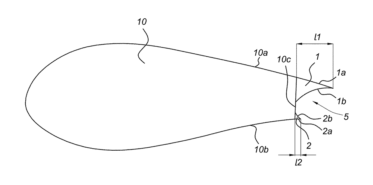
[0018]FIG. 1 shows a cross sectional view of a flat-back airfoil 10 along the airflow direction of e.g. the wind turbine ro...


PUM


Abstract

Aerodynamic element having a cross section in an airflow direction with a suction side surface, a pressure side surface, and a trailing edge extending between the suction side surface and the pressure side surface. The aerodynamic element further comprises an extension body attached to the trailing edge near the suction side surface of the aerodynamic element. A top surface of the extension body is flush with the suction side surface. The aerodynamic element (10) is e.g. applied in a rotor blade for a wind turbine.

Description

FIELD OF THE INVENTION[0001]The present invention relates to an aerodynamic element, e.g. for a wind turbine rotor blade, having a cross section in an airflow direction with a trailing edge of the flat-back airfoil (or blunt railing edge) type. The aerodynamic element may also be provided in other applications, such as wing bodies, etc. In a further aspect, the present invention relates to a rotor blade of a wind turbine.PRIOR ART[0002]Blunt trailing edge or flat-back airfoils are examples of aerodynamic elements used in many aerodynamic applications, meeting the structural and volume requirements of these applications, such as in blended wing-body aircraft, unmanned aerial vehicles and wind turbine blades. Further modifications to flat-back airfoils are known in the art to address associated problems. One of these modifications is the usage of active flow control devices like micro-tabs, synthetic jets and micro-flaps (usually referred as smart controls). These devices are able to ...

Claims


Application Information

Patent Timeline
IPC IPC(8): F03D1/06F03D7/02
CPCF03D1/0641F03D7/0232F03D7/024F05B2240/301F05B2250/712F05B2240/3052Y02E10/72B64C3/14B64C2003/147
Inventor GRASSO, FRANCESCO
Owner NEDERLANDSE ORG VOOR TOEGEPAST-NATUURWETENSCHAPPELIJK ONDERZOEK (TNO)
Why Eureka
Try Eureka