Electric vacuum pump, in particular for arranging in a vehicle

Active Publication Date: 2018-08-23
HELLA KGAA HUECK & CO
2 Cites 0 Cited by

AI-Extracted Technical Summary

Problems solved by technology

In particular, when the outlet connection is located directly on the motor flange, there is the risk of water entering the pump part.
This risk is particularly high when the outlet connection is located at the low point of the motor flange with respect to the vacuum pump installation position.
Because a connection channel attaches to the outlet connection on the inside of the motor flange...

Benefits of technology

[0006]It is therefore an object of the present invention to provide an electric vacuum pump with an increased lifetime. In particular, it is the object to refine an electric vacuum pump in such a way...

Abstract

An electric vacuum pump, in particular for arrangement in a vehicle, having an electric motor and a pump part, which can be driven by the electric motor, so that air can be drawn into the pump part from a suction connection and wherein air can be taken out of the pump part out of an outlet connection. A motor flange is provided on which the pump part rests, and the outlet connection is disposed on the motor flange. A receiving space is formed in the motor flange into which space the outlet connection opens, and a rubber-elastic insert part, which has a hollow inner region which communicates with the outlet connection, is accommodated in the receiving space. The insert part has at least one air guide opening via which air can flow from the pump part into the inner region.

Application Domain

Positive displacement pump componentsRotary piston pumps +7

Technology Topic

EngineeringFlange +2

Image

  • Electric vacuum pump, in particular for arranging in a vehicle
  • Electric vacuum pump, in particular for arranging in a vehicle
  • Electric vacuum pump, in particular for arranging in a vehicle

Examples

  • Experimental program(1)

Example

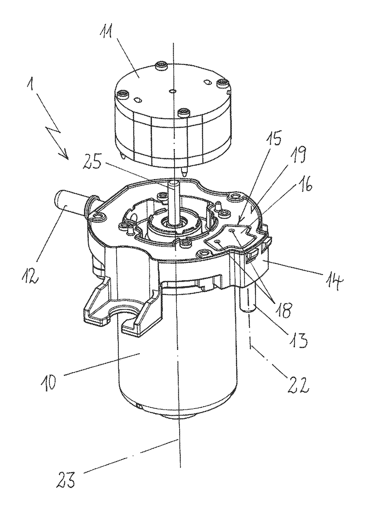
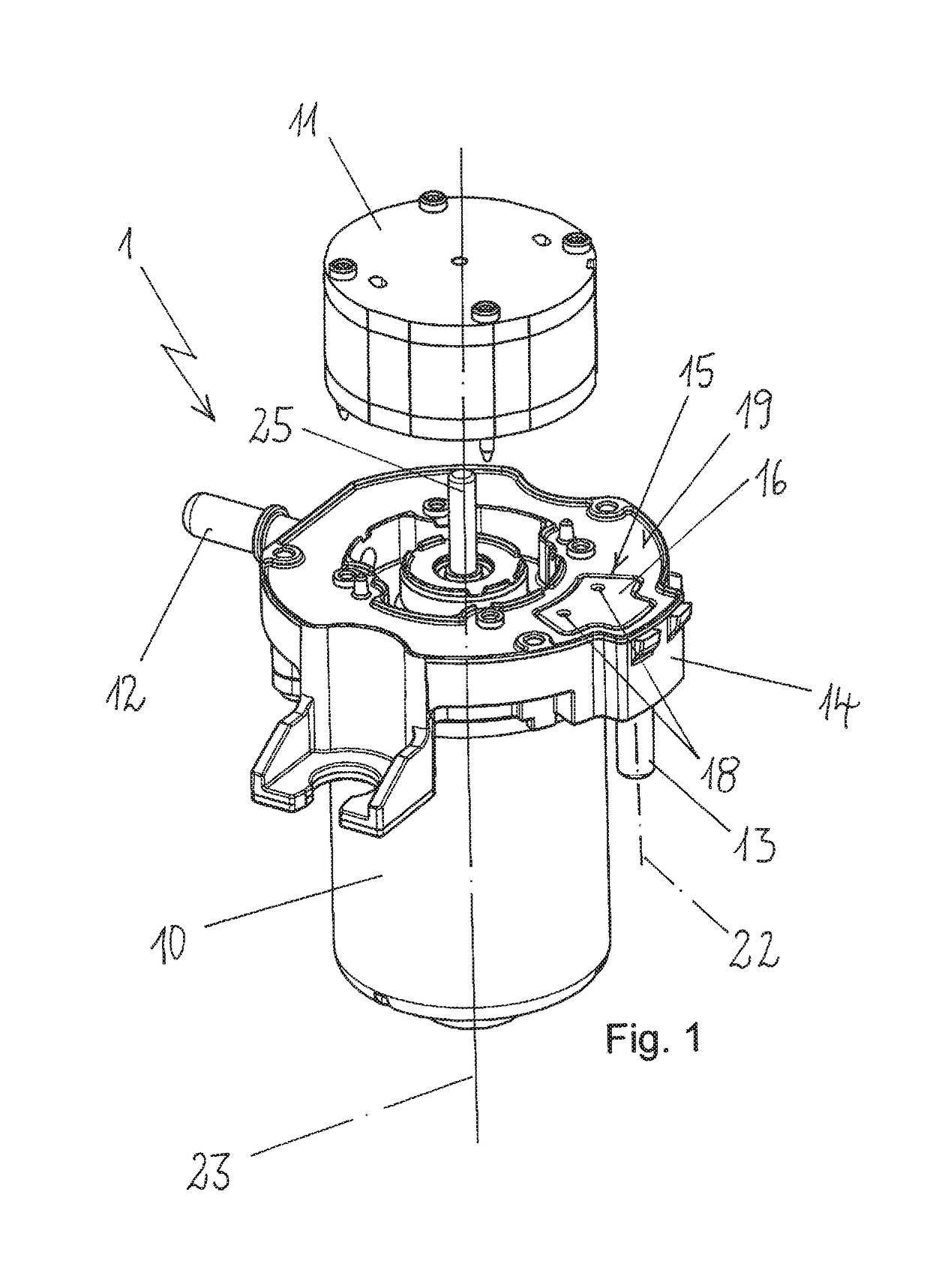
[0023]FIG. 1 shows in a perspective view an electric vacuum pump 1 comprising an electric motor 10 and comprising a pump part 11, and the electric motor 10 has a motor shaft 25 which runs along a motor axis 23. Electric motor 10 has a substantially cylindrical shape and has on the upper side a motor flange 14 from which motor shaft 25 protrudes, and when pump part 11 is mounted on end face 19 of motor flange 14, motor shaft 25 projects into pump part 11 and drives it during operation of vacuum pump 1. The pump part 11 can be designed, for example, as a vane cell pump. During operation of electric vacuum pump 1, it draws in air via suction connection 12, and the drawn-in air is provided compressed via outlet connection 13. The illustrated design of electric vacuum pump 1 has an outlet connection 13 which extends with its extension axis 22 on the outside to motor 10 approximately parallel to motor axis 23. In contrast, suction connection 12 protrudes from motor flange 14 approximately perpendicularly to motor axis 23.
[0024]Starting from end face 19, a receiving space 15 is formed in motor flange 14, in which space a rubber-elastic insert part 16 is inserted. Insert part 16 has a shape which substantially completely fills the contour of receiving space 15. On the upper side, insert part 16 has air guide openings 18 by which an air connection of insert part 16 to pump part 11 is created. The inner region of insert part 16 in this case communicates with outlet connection 13, wherein air guide openings 18 are closer to motor axis 23 than outlet connection 13 with its extension axis 22.
[0025]FIG. 2 shows a top plan view of motor flange 14 in the region of receiving space 15 which is introduced into motor flange 14 and in which rubber-elastic insert part 16 can be inserted. The top plan view shows outlet connection 13, which opens into receiving space 15.
[0026]FIG. 3 shows a cross-sectional view of motor flange 14 in the region of receiving space 15 in which rubber-elastic insert part 16 is inserted. The cross-sectional view shows a fluidic connection of outlet connection 13 to inner region 17 of insert part 16. Air duct opening 18 introduced into insert part 16 has the offset 21 to extension axis 22 of outlet connection 13, and if outlet connection 13 is located on a bottom side due to the mounting position of vacuum pump 1, offset 21 thus forms a height offset. If water penetrates into outlet connection 13, then it essentially only reaches inner region 17, but the water does not enter air guide opening 18.
[0027]Insert part 16 on the side opposite to the arrangement of electric motor 10 on motor flange 14 has a top surface 24, and if the pump part is mounted on motor flange 14, top surface 24 terminates with the pump part and seals against it. In the same way, insert part 16 seals against the edge of receiving space 15, in particular when insert part 16 is slightly oversized with respect to the dimensions of receiving space 15.
[0028]FIG. 4 shows a first perspective view of rubber-elastic insert part 16, and FIG. 5 shows a further perspective view of insert part 16 from a bottom side, so that inner region 17 is shown. The outer region of insert part 16 terminates with a circumferential lateral surface 20, which can seal against the wall of receiving space 15. On the upper side, air guide openings 18 open into the area to which pump part 11 connects when insert part 16 is arranged in receiving space 15 and when pump part 11 is seated on motor flange 14.
[0029]The bottom view of insert part 16 shows air guide openings 18 with a contour that opens conically toward inner region 17, as a result of which arising noise during operation of the vacuum pump is minimized.
[0030]The invention is not limited in its execution to the preferred exemplary embodiment described above. Rather, a number of variants are conceivable which make use of the illustrated solution in fundamentally different embodiments as well. All features and/or advantages emerging from the claims, description, or drawings, including structural details and spatial arrangements, can be essential to the invention both alone and in the most diverse combinations.
[0031]The invention being thus described, it will be obvious that the same may be varied in many ways. Such variations are not to be regarded as a departure from the spirit and scope of the invention, and all such modifications as would be obvious to one skilled in the art are to be included within the scope of the following claims.

PUM

PropertyMeasurementUnit
Gravity
Distance
Deformation enthalpy

Description & Claims & Application Information

We can also present the details of the Description, Claims and Application information to help users get a comprehensive understanding of the technical details of the patent, such as background art, summary of invention, brief description of drawings, description of embodiments, and other original content. On the other hand, users can also determine the specific scope of protection of the technology through the list of claims; as well as understand the changes in the life cycle of the technology with the presentation of the patent timeline. Login to view more.

Similar technology patents

Method and device for wire cutting of a material

InactiveUS20160243725A1reduce riskincrease life time
Owner:COMMISSARIAT A LENERGIE ATOMIQUE ET AUX ENERGIES ALTERNATIVES

Linear moving bearing

ActiveUS20190360525A1high enduranceincrease life time
Owner:SHIH JOHN WUN CHANG

Means for securing jaw plates in a jaw crusher

InactiveUS20150174580A1increase life timeassembly and disassembly be simplify
Owner:SANDVIK INTELLECTUAL PROPERTY AB

Process for producing propylene oxide

InactiveUS20120130096A1increase life timereduces plug
Owner:CRAMPTON HANNAH L +5

Classification and recommendation of technical efficacy words

  • increase life time
  • prevent water penetration

Beverage dispenser

InactiveUS20060005712A1increase life timeminimize thermal degradation
Owner:GREENWALD TECH

Gas turbine blade cooling circuits

InactiveUS20030044277A1temperature limitationincrease life time
Owner:SN DETUDE & DE CONSTR DE MOTEURS DAVIATION S N E C M A

Charge/Discharge Control Device and Power Generation System

InactiveUS20120239214A1increase life timesuppress fluctuation
Owner:SANYO ELECTRIC CO LTD

Electronic device package, module, and electronic device

ActiveUS20100246144A1electrical resistance decreaseincrease life time
Owner:GK BRIDGE 1

Mounting method with detachable rubber water stop mounted inside

InactiveCN101372840Aprevent water penetrationstable installation
Owner:SHANGHAI RES INST OF BUILDING SCI CO LTD

Polymer cement waterproof paint

ActiveCN103449785Agood adhesionprevent water penetration
Owner:XIAMEN LIKASAM WATERPROOF ENG

Air sterilization card

InactiveCN109646699Aprevent water penetrationAvoid drug failure
Owner:毛文静

Manufacturing method for electronic device

ActiveUS20200266381A1prevent water penetrationprevent permeation of water
Owner:KONICA MINOLTA INC
Why Eureka
Try Eureka