Dynamic physical register allocation across multiple threads

a register allocation and physical register technology, applied in the field of processor threads, can solve the problems of declining efficiency of processing cores, and achieve the effect of improving the overall system performan

Active Publication Date: 2018-08-23
IBM CORP
View PDF4 Cites 16 Cited by
  • Summary
  • Abstract
  • Description
  • Claims
  • Application Information

AI Technical Summary

Benefits of technology

[0005]According to an exemplary embodiment of the invention, a computer system is provided including a processor and a main memory. The processor includes a plurality of hardware threads configured to execute a plurality of software threads. The processor executes an instruction set that defines a set of architected registers that a compiler may use in compiling an application. The main memory includes a first register table configured to contain the set of architected registers for the currently running software threads. The processor includes a second register table configured to contain a subset of the architected registers and a mapping table for each software thread indicating whether the valid contents for each of its architected registers is currently in the first register table or the second register table. The processor may include a controller that monitors the current usage of registers by the software threads and notifies each software thread whether the overall system performance could be improved by recompiling the thread to use a different number of architected registers, lower or higher than the number of architected registers that it is currently compiled to.

Problems solved by technology

However, the efficiency of processing cores is increasingly declining due to a memory wall problem that describes the relatively long stall latency that processor cores will experience on cache misses due to memory latency.

Method used


Image

  • Dynamic physical register allocation across multiple threads
  • Dynamic physical register allocation across multiple threads
  • Dynamic physical register allocation across multiple threads

Examples


Embodiment Construction

[0016]The inventive concept will be described in more detail with reference to the accompanying drawings, where exemplary embodiments of the present disclosure have been illustrated. Throughout the drawings, same or like reference numerals are used to represent the same or like components. However, the present inventive concept can be implemented in various manners, and thus should not be construed to be limited to the embodiments disclosed herein. On the contrary, those embodiments are provided for the thorough and complete understanding of the present disclosure to convey the scope of the present disclosure to those skilled in the art.

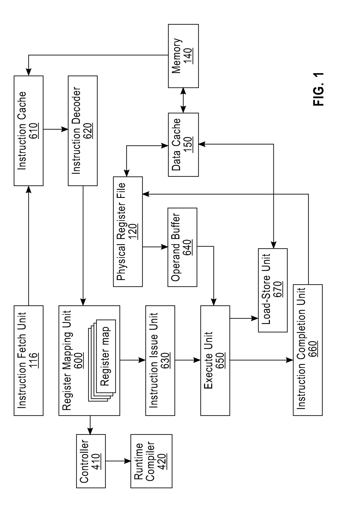
[0017]FIG. 1 illustrates an example system for managing threads. The instruction fetch unit 116 fetches instructions from memory 140 through the instruction cache 610. Fetched instructions are decoded using the instruction decoder 620. In the process of decoding, the architected registers needed by the instruction either as source operands or as dest...


PUM


Abstract

A computer system includes a processor, main memory, and controller. The processor includes a plurality of hardware threads configured to execute a plurality of software threads. The main memory includes a first register table configured to contain a current set of architected registers for the currently running software threads. The controller is configured to change a first number of the architected registers assigned to a given one of the software threads to a second number of architected registers when a result of monitoring current usage of the registers by the software threads indicates that the change will improve performance of the computer system. The processor includes a second register table configured to contain a subset of the architected registers and a mapping table for each software thread indicating whether the architected registers referenced by the corresponding software thread are located in the first register table or the second register table.

Description

BACKGROUND1. Technical Field[0001]The present disclosure relates generally to processors, and more specifically to processor threads.2. Discussion of Related Art[0002]Modern applications are comprised of a large set of software threads (executable tasks) that need to be dispatched to a finite set of hardware threads. This has traditionally been the responsibility of the operating system (OS). The operating system can maintain one or more run queues of executable tasks and time-shares this set of executable tasks over the available hardware threads.[0003]Processing cores may include one or more of the hardware threads. However, the efficiency of processing cores is increasingly declining due to a memory wall problem that describes the relatively long stall latency that processor cores will experience on cache misses due to memory latency. Hence, computer architectures attempt to ‘hide’ the memory latency by executing different instruction streams when stalls are experienced.[0004]The...

Claims


Application Information

Patent Timeline
Patent Type & Authority Applications(United States)
IPC IPC(8): G06F9/30G06F13/24
CPCG06F9/30098G06F13/24G06F9/30145G06F9/30123G06F9/3851G06F9/384G06F2209/5018G06F2209/507G06F9/5027G06F8/4442G06F8/441G06F9/50G06F9/3012G06F9/45516G06F9/30138
Inventor CAIN, III, HAROLD W.FRANKE, HUBERTUSJOHNS, CHARLES R.LE, HUNG Q.NAIR, RAVI
Owner IBM CORP
Why Eureka
Try Eureka