
Imaging apparatus, control method for an imaging apparatus, and program

Active Publication Date: 2018-08-30
CANON KK
View PDF4 Cites 1 Cited by
  • Summary
  • Abstract
  • Description
  • Claims
  • Application Information

AI Technical Summary

Benefits of technology

The present invention aims to provide an imaging apparatus that can quickly and stably capture images to adjust the condition for acquiring information on an object to be inspected. This is achieved by scanning a light beam to create a Lissajous figure or other shape to obtain the information. The control method for the imaging apparatus and the accompanying program make this process easy and efficient.

Problems solved by technology

As a result, it is difficult to acquire tomographic information from the same spot.

Method used


Image

  • Imaging apparatus, control method for an imaging apparatus, and program
  • Imaging apparatus, control method for an imaging apparatus, and program
  • Imaging apparatus, control method for an imaging apparatus, and program

Examples


first embodiment

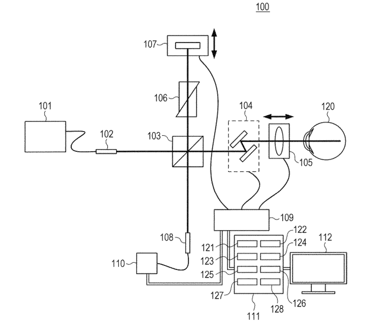
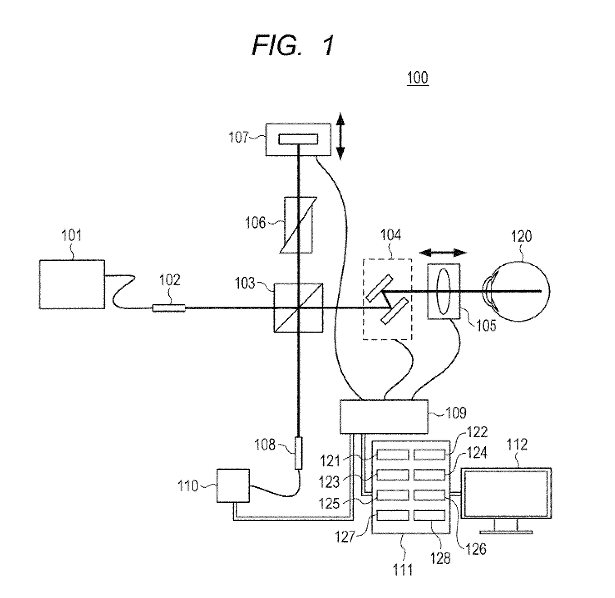
[0066]As a specific embodiment of the present invention, there is described a first embodiment of the present invention in which tomographic information is acquired from a retina of a human eye (fundus of the eye 120 to be inspected) being an object to be inspected. In this case, the description is given on the assumption that driving waveforms expressed by Expression 2 are applied to drive the two galvano scanners.

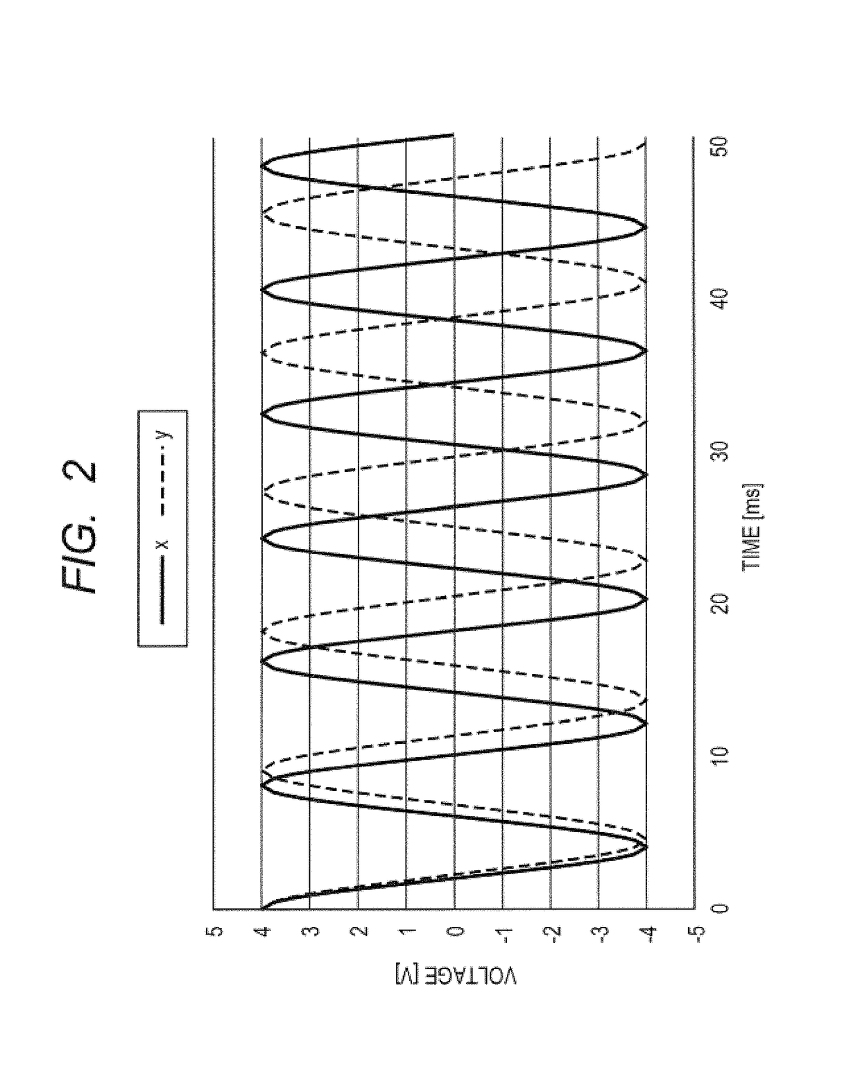
f(t)={Axcos(2πfAti#A)Aycos((2#A-4)πfAti#A2)(Expression2)

[0067]In Expression 2, Ax and Ay are adjusted by the control apparatus 109 so that a measuring beam is scanned so as to draw a Lissajous figure over an area of 6×6 mm on the fundus of the eye 120 to be inspected, and ti represents a sampling time to acquire the i-th piece of tomographic information. Now, assuming that the number of samples DA per loop is 1,024, the sampling is executed at #A2 / 2=524,288 points from an entire scanning range. In this case, assuming that the acquisition rate for tomographic information u...

second embodiment

[0101]In the first embodiment described above, before the execution of the main imaging, a measuring beam is repeatedly scanned along a scan line having, for example, a linear shape within an imaging range (acquisition range of the three-dimensional tomographic information), and the displaying of a tomographic image obtained by the scan line is continuously repeated. With this configuration, the imaging condition to be used at the time of the main imaging can be adjusted with reference to the tomographic image in advance, which allows enhancement of the image quality of an image obtained through the main imaging. However, it is conceivable that, even when the main imaging is performed under an appropriate imaging condition, appropriate tomographic information cannot be acquired at the time of the main imaging due to, for example, nictation, which degrades the image quality of the image obtained through the imaging. In a second embodiment of the present invention, an occurrence of ni...

third embodiment

[0109]The first embodiment is described above by taking an example of the Lissajous scan for drawing a Lissajous figure by a measuring beam in main imaging. However, the present invention does not lose an effect even when a measuring beam is scanned on a fundus so as to draw a Lissajous-like figure similar to a Lissajous figure. The effect of the present invention is not limited to the mode of drawing a figure by a measuring beam based on a pure Lissajous figure, that is, a combination of a scan in the X direction and a scan in the Y direction that are described as strict simple harmonic motions. That is, the same effect can be produced even by scanning a measuring beam based on a Lissajous-like figure or figure group, which is obtained in such a mode that the respective scans in different two directions are described as reciprocation so as to cover all the imaging range. The following description is directed to a third embodiment of the present invention in which a measuring beam i...


PUM


Abstract

Provided is an imaging apparatus including: a first scanning unit and a second scanning unit, subjecting a measuring beam, which is obtained by splitting a light source beam, to a back-and-forth scan in a predetermined area on a fundus in a first direction and a second direction, respectively; a scanning control unit controlling the first scanning unit and the second scanning unit so as to simultaneously execute scans; a depth information acquisition unit obtaining information on the fundus in a depth direction based on interference beam between return beam from the fundus and a reference beam; an image generation unit generating a tomographic image in the predetermined area through use of output from the depth information acquisition unit and a control signal supplied by the scanning control unit; and a display unit displaying the generated image. In the imaging apparatus, a tomographic image along a freely-set line within the predetermined area can be generated through use of the output from the depth information acquisition unit, and Is repeatedly displayed on the display unit before depth information is acquired through the back-and-forth scans simultaneously executed by the two scanning units.

Description

BACKGROUND OF THE INVENTIONField of the Invention[0001]The present invention relates to an imaging apparatus configured to obtain an image of an object to be inspected by scanning a light beam on the object to be inspected, a control method for an imaging apparatus, and a program.Description of the Related Art[0002]Currently, as a method of noninvasively observing an internal structure of an eye, there is used an optical coherence tomographic apparatus (hereinafter referred to as “OCT apparatus”) using optical coherence tomography (hereinafter referred to as “OCT”) to which an optical interference phenomenon is applied. In the OCT apparatus, a light beam emitted from a low-coherence and near-infrared light source is split into a measuring beam and a reference beam. Then, scattered reflected beam from an eye irradiated with the measuring beam is caused to interfere with the reference beam, to thereby obtain tomographic information that is high in resolution and high in sensitivity in...

Claims


Application Information

Patent Timeline
IPC IPC(8): A61B3/10A61B3/12A61B3/14
CPCA61B3/102A61B3/12A61B3/14A61B3/0041A61B3/0058
Inventor FUKUHARA, MAKOTOSAKAGAWA, WATARUYUASA, TAKASHI
Owner CANON KK
Features
  • Generate Ideas
  • Intellectual Property
  • Life Sciences
  • Materials
  • Tech Scout
  • Unparalleled Data Quality
  • Higher Quality Content
  • 60% Fewer Hallucinations
Learn More