
Glaucoma drainage implant

Active Publication Date: 2018-09-06
NIKOLIC MED STEPHAN DR
View PDF0 Cites 7 Cited by
  • Summary
  • Abstract
  • Description
  • Claims
  • Application Information

AI Technical Summary

Benefits of technology

The glaucoma drainage implant described in this patent provides several technical effects. Firstly, it prevents fibrotic encapsulation of the pressure relief valve by using an actuation area that can be non-invasively opened and closed. Secondly, it avoids the use of cytotoxic drugs to prevent late-onset sterile endophthalmitis. Thirdly, it allows for non-invasive and automatic opening and closing of the pressure relief valve by inputting heat into the actuation area. Fourthly, it can be designed in a compact and low-maintenance way, with a thin and wide base plate. Fifthly, it helps to prevent sticking of the conjunctiva and pressure relief flap by using a step-shaped base plate. Finally, it allows for surface structuring on the pressure relief flap to regulate intraocular pressure.

Problems solved by technology

Implants without a valve involve the additional risk of postoperative hypotonia due to the lack of closure following a lowering of pressure.
This can lead not only to clogging of a glaucoma drainage implant placed in the eye, but also to growth of a scleral flap created during implant surgery to ensure filtration.
This prevents the desired drainage of aqueous humor, thus resulting in a further increase in intraocular pressure.
Absorption of radiation by the material of the implant or part of the implant results in the increase in temperature.

Method used


Image

  • Glaucoma drainage implant
  • Glaucoma drainage implant
  • Glaucoma drainage implant

Examples


Embodiment Construction

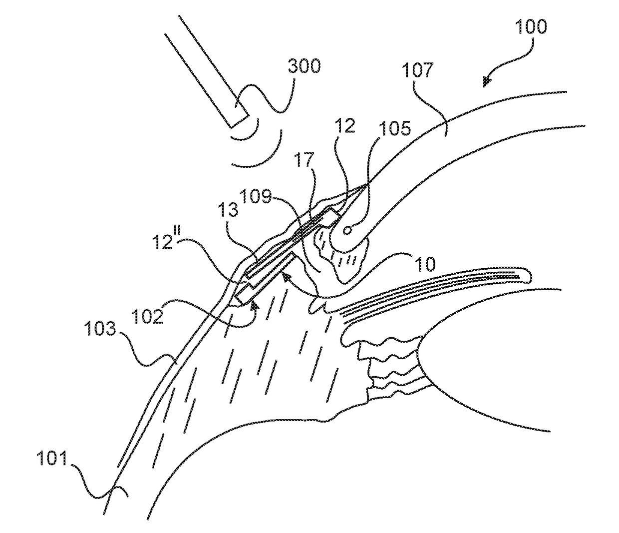
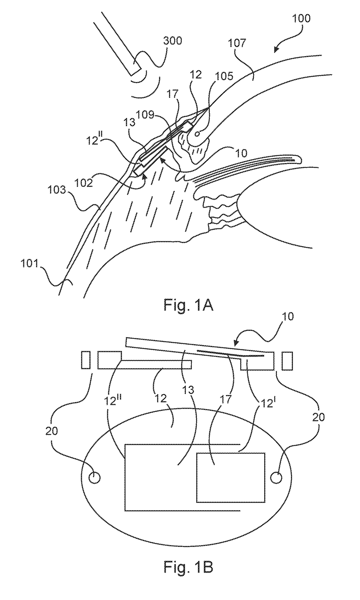
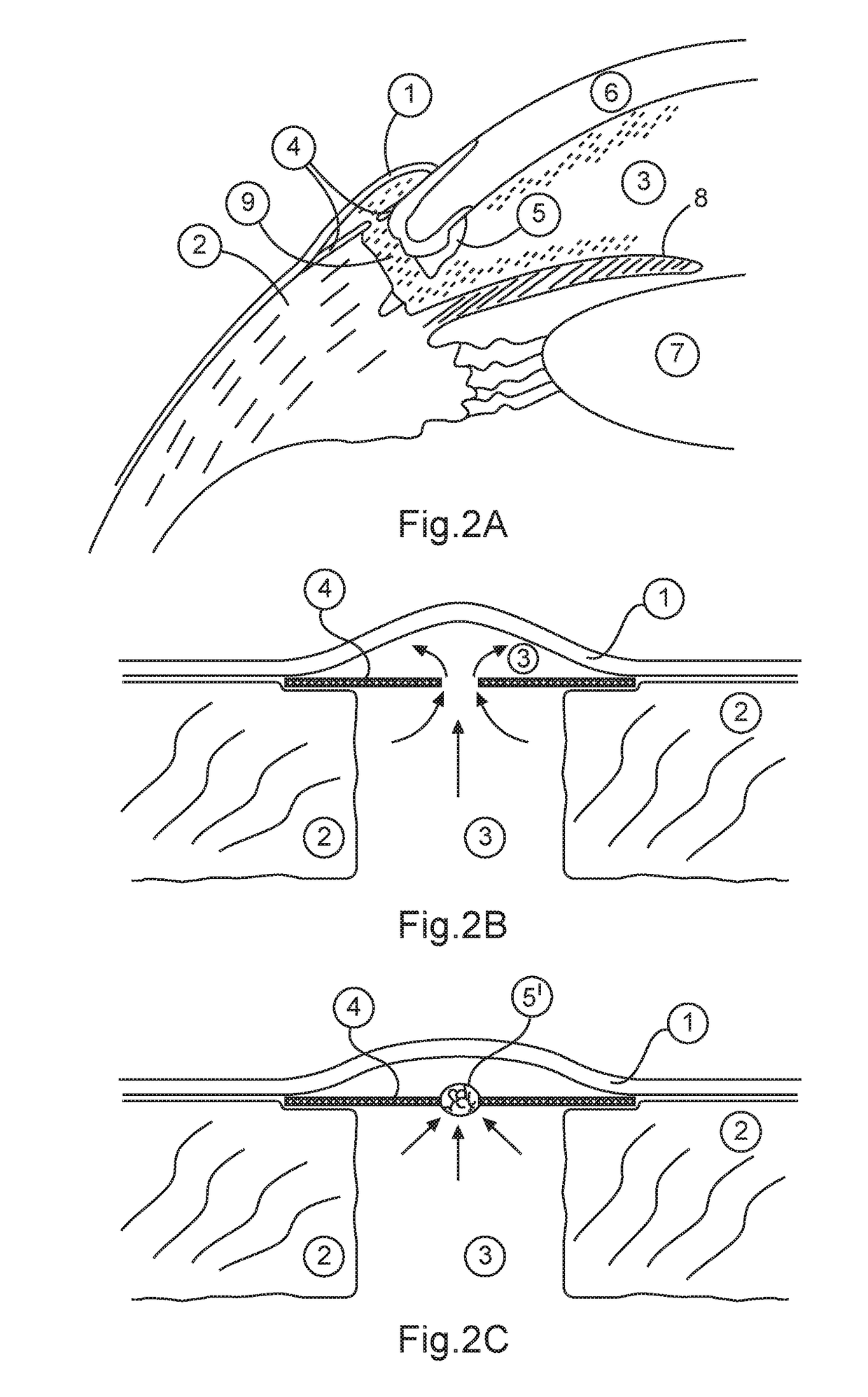
[0033]In the Figures, the same or corresponding elements or units are each provided with the same and / or the corresponding reference signs. When an element or a unit has already been described with reference to a particular Figure, a detailed description is dispensed with when discussing another Figure. However, it is to be understood that the present disclosure may assume various alternative orientations and step sequences, except where expressly specified to the contrary. It is also to be understood that the specific devices and processes illustrated in the attached drawings, and described in the following specification, are simply exemplary embodiments of the inventive concepts defined in the appended claims. Hence, specific dimensions and other physical characteristics relating to the embodiments disclosed herein are not to be considered as limiting, unless the claims expressly state otherwise. The drawings referenced herein are schematic and associated views thereof are not nec...


PUM


Abstract

A glaucoma drainage implant comprising a pressure relief valve via which aqueous humor can be drained. The pressure relief valve has a pressure relief flap which is movably connected with a base plate of the implant, which is to be embedded in a sclera, wherein the pressure relief flap has an actuation area by means of which the pressure relief flap can be mobilized non-invasively during a post-operative healing phase or thereafter. The actuation area is preferably designed as a thermomechanically active area.

Description

CROSS-REFERENCE TO FOREIGN PRIORITY APPLICATION[0001]The present application claims the benefit under 35 U.S.C. §§ 119(b), 119(e), 120, or 365(c) of DE 02017104543.0 filed Mar. 3, 2017.FIELD OF THE INVENTION[0002]The present invention relates to a glaucoma drainage implant comprising a pressure relief valve via which the aqueous humor can be drained.BACKGROUND OF THE INVENTION[0003]Glaucoma is one of the most frequent causes of blindness worldwide. It produces an irreversible degeneration of the retinal ganglion cells. If medication or laser treatment fails to take effect, the underlying increase in intraocular pressure must be lowered by a surgical procedure. The most frequently used method in this regard is trabeculectomy. If the latter fails or is contraindicated, the use of drainage implants is the means of choice.[0004]A general distinction can be made, with regard to current implants, between systems with and systems without a valve. Implants without a valve involve the additi...

Claims


Application Information

Patent Timeline
IPC IPC(8): A61F9/007A61F9/00
CPCA61F9/00781A61F9/0017A61F2009/00865A61F2240/001A61F2009/00891A61F9/00736A61M27/002A61F2210/0047
Inventor LUBATSCHOWSKI, HOLGER
Owner NIKOLIC MED STEPHAN DR
Learn More