Pulse wave transit time measurement device and living body state estimation device

a technology of transit time and measurement device, which is applied in the field of pulse wave transit time measurement device and living body state estimation device, can solve the problems of difficult stably performing measurement, measurement error of pulse wave transit time, and measurement error of pulse wave transit time, and achieve accurate estimation, continuous calculation, and higher stability

Pending Publication Date: 2018-09-13
MURATA MFG CO LTD
View PDF12 Cites 5 Cited by
  • Summary
  • Abstract
  • Description
  • Claims
  • Application Information

AI Technical Summary

Benefits of technology

[0034]The pulse wave transit time greatly fluctuates depending on the distance from the heart of the location at which the pulse wave signal is obtained, and it fluctuates even with slight changes of the posture. In the above-described case, however, when the pulse wave transit time is measured, the deviation in angle between the posture of the user and the reference posture is calculated based on the result of the calibration performed in advance. When the value of the blood pressure is calculated from the pulse wave transit time, the distance from the heart to the pulse-wave measurement location is determined based on both of the calcula

Problems solved by technology

More specifically, although the pulse wave signal is obtained from, for example, the earlobe in the device disclosed in Japanese Unexamined Patent Application Publication No. 2014-105, the pulse wave transit times when the user is in the left and right lateral decubitus positions, for example, are different and a measurement error of the pulse wave transit time is generated depending on whether the pulse wave signal is obtained from the left or right earlobe.
Similarly, although the pulse wave signal is obtained from the carotid artery in Japanese Unexamined Patent Application Publication No. 2001-161649, the pulse wave transit times when the user is in the left and right lateral decubitus positions, for example, are

Method used


Image

  • Pulse wave transit time measurement device and living body state estimation device
  • Pulse wave transit time measurement device and living body state estimation device
  • Pulse wave transit time measurement device and living body state estimation device

Examples


Embodiment Construction

[0042]Preferred embodiments of the present invention will be described in detail below with reference to the drawings. In the drawings, the same or equivalent components are denoted by the same reference signs. Furthermore, the same elements are denoted by the same reference signs in the drawings, and duplicate explanation of the same elements is omitted. The following description is provided in connection with a case in which a pulse wave transit time measurement device is applied to a blood pressure fluctuation estimation device (corresponding to “a living body state estimation device”).

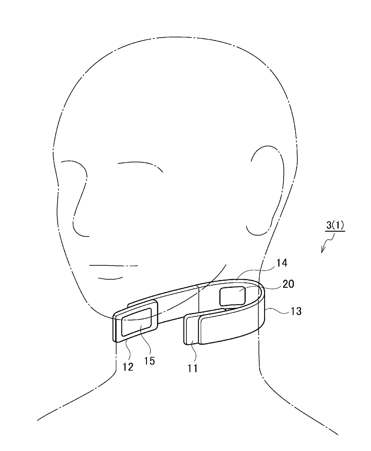
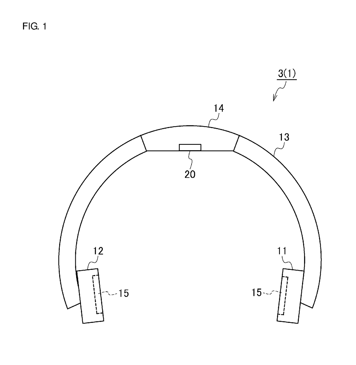
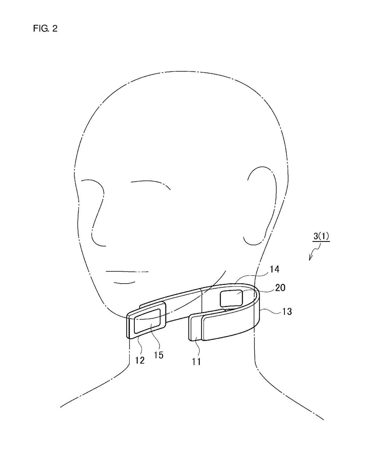
[0043]First, a configuration of a blood pressure fluctuation estimation device 3 including a pulse wave transit time measurement device 1 according to a preferred embodiment is described with reference to FIGS. 1 to 3. FIG. 1 is a plan view illustrating an external appearance of the blood pressure fluctuation estimation device 3 of neck band type including the pulse wave transit time measurement de...


PUM


Abstract

A pulse wave transit time measurement device includes a neck band, a pair of electrocardiographic electrodes detecting an electrocardiographic signal, a photoplethysmographic sensor detecting a pulse wave signal, and a pulse wave transit time calculator calculating a pulse wave transit time based on a peak time difference between the electrocardiographic signal detected by the electrocardiographic electrodes and the pulse wave signal detected by the photoplethysmographic sensor. The photoplethysmographic sensor is positioned in or substantially in a central region of the neck band at a location at which the photoplethysmographic sensor is in contact with a neck of a user at or near a midline of the neck on the backside when the neck band is worn around the neck of the user.

Description

CROSS REFERENCE TO RELATED APPLICATIONS[0001]This application claims the benefit of priority to Japanese Patent Application No. 2015-225210 filed on Nov. 17, 2015 and is a Continuation Application of PCT Application No. PCT / JP2016 / 080797 filed on Oct. 18, 2016. The entire contents of each application are hereby incorporated herein by reference.BACKGROUND OF THE INVENTION1. Field of the Invention[0002]The present invention relates to a pulse wave transit time measurement device that measures a pulse wave transit time, and to a living body state estimation device including the pulse wave transit time measurement device.2. Description of the Related Art[0003]Recently, a pulse wave transit time representing a time taken for a pulse wave to transit in arteries inside a living body (e.g., a time from an R wave to the appearance of a pulse wave in an electrocardiogram) and reflecting change of blood pressure has been used as an index in, for example, evaluation of arterial stiffness and es...

Claims


Application Information

Patent Timeline
IPC IPC(8): A61B5/024A61B5/0456A61B5/00A61B5/332A61B5/352
CPCA61B5/02427A61B5/0456A61B5/6822A61B5/7264A61B5/02444A61B5/1116A61B5/022A61B2560/0223A61B5/04017A61B5/6831A61B5/721A61B5/0022A61B5/02125A61B5/1071A61B5/14542A61B2560/0204A61B2562/0204A61B2562/0219A61B2562/0271A61B2562/029A61B5/7278A61B5/316A61B5/282A61B5/352A61B5/346
Inventor SHIMUTA, TORU
Owner MURATA MFG CO LTD
Why Eureka
Try Eureka