Electromechanical Brake Force Booster

Active Publication Date: 2018-09-13
LUCAS AUTOMOTIVE GMBH +1
View PDF9 Cites 7 Cited by
  • Summary
  • Abstract
  • Description
  • Claims
  • Application Information

AI Technical Summary

Benefits of technology

[0008]An electromechanical brake force booster with a compact construction

Problems solved by technology

The compact construction of the gearing can thus lead to a drive arrangement of an electromechani

Method used


Image

  • Electromechanical Brake Force Booster
  • Electromechanical Brake Force Booster
  • Electromechanical Brake Force Booster

Examples


Example

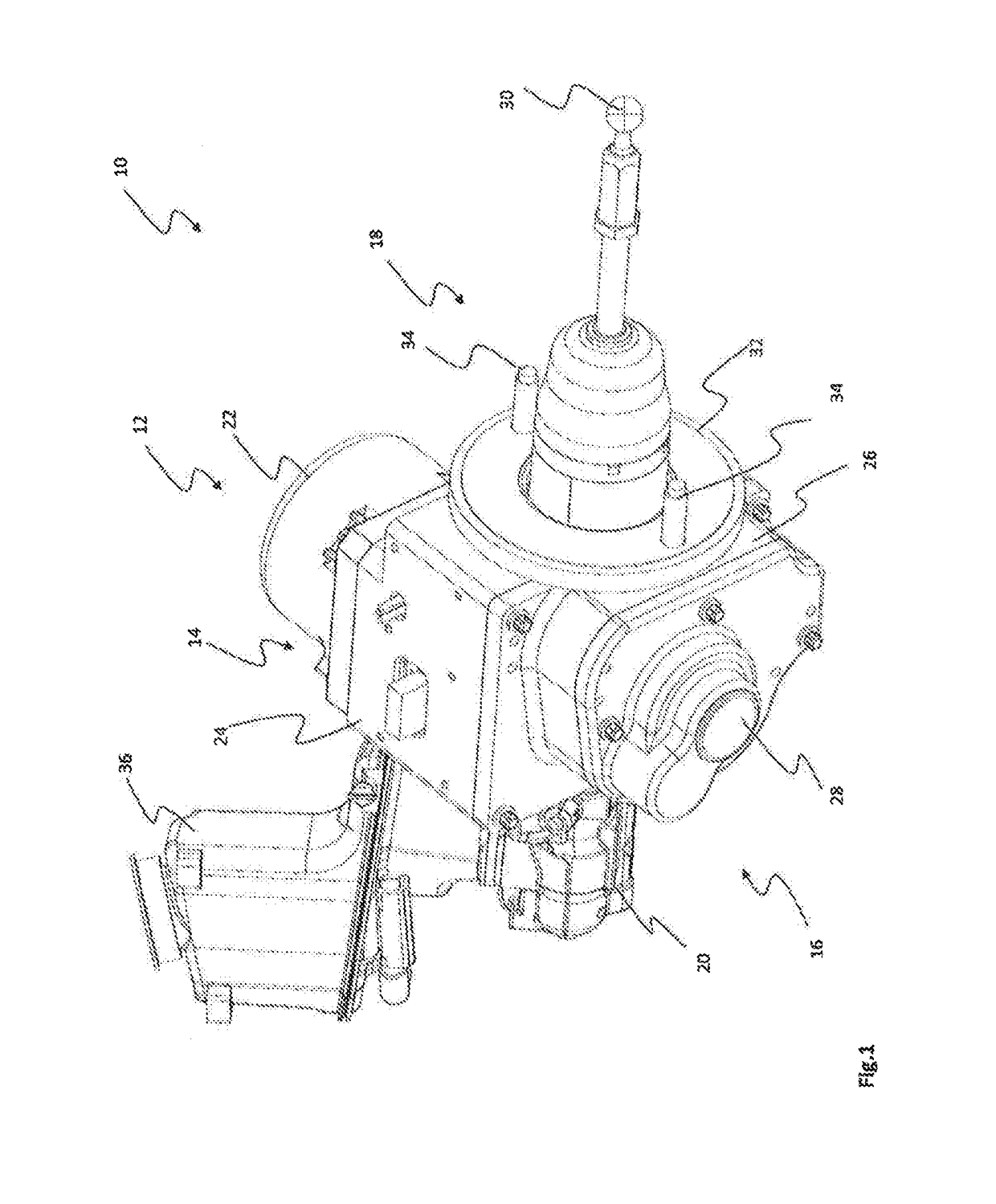
[0045]FIG. 1 shows a perspective view of an electromechanical brake force booster which is denoted in general by 10.

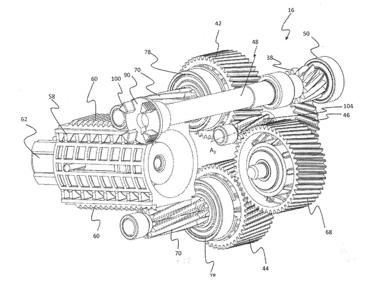
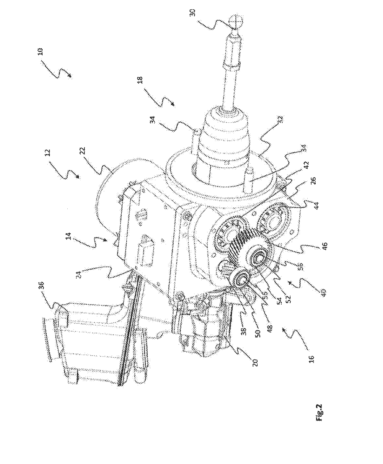
[0046]The electromechanical brake force booster 10 comprises a motor 12, a control unit 14, a gearing 16 and an actuating device 18. The actuating device 18 is coupled to a brake cylinder 20.

[0047]The brake force booster 10 has a multipart housing with housing parts 22, 24, 26 and 28. The housing parts 22 and 24 are assigned to the motor 12, the control unit 14 and the actuating device 18. The housing parts 26 and 28 serve for receiving the gearing 14. The motor 12 is arranged on a side of the actuating device 18 that faces away from the side of the actuating device with the gearing 16. The electromechanical brake force booster 10 and the brake cylinder 20 form an assembly.

[0048]The actuating device 18 has an actuating member 30 which is actuatable via a pedal force produced by a driver of the vehicle, and serves for actuating the brake cylinder 20 and the electromecha...


PUM


Abstract

The electromechanical brake force booster for a vehicle brake system comprises a drive arrangement for driving at least one actuating device which is designed for actuating a brake cylinder. The drive arrangement has at least one electric motor and a gearing for coupling the electric motor to the at least one actuating device. The gearing comprises at least one second spur gear and at least one first spur gear. Furthermore, the gearing has an intermediate gearing stage. The intermediate gearing stage couples the electric motor to the second spur gear and to the first spur gear in torque-transmitting fashion. The intermediate gearing stage drives the second spur gear directly and the first spur gear via at least one intermediate gear.

Description

CROSS-REFERENCE TO RELATED APPLICATIONS[0001]This application is the National Phase of International Application PCT / EP2016 / 072052 filed Sep. 16, 2016 which designated the U.S. and that International Application was published in English under PCT Article 21(2) on Mar. 23, 2017 as International Publication Number WO 2017 / 046380 A1. PCT / EP2016 / 072052 claims priority to German Applications No. 10 2015 012 124.3, filed Sep. 17, 2015, and No. 10 2015 012 125.1, filed Sep. 17, 2015. Thus, the subject nonprovisional application claims priority to DE 10 2015 012 124.3 and DE 10 2015 012 125.1, filed Sep. 17, 2015. The disclosures of aforementioned applications are incorporated herein by reference.BACKGROUND OF THE INVENTION[0002]The present disclosure relates in general to the technical field of electrohydraulic brake force generating devices. It relates in particular to an electromechanical brake force booster which can be used in an electrohydraulic brake force generating device.[0003]Ele...

Claims


Application Information

Patent Timeline
IPC IPC(8): B60T8/48F16H1/22B60T13/74
CPCB60T8/4854F16H1/225B60T13/745B60T13/741B60T13/746F16H19/04F16H1/22F16H35/18
Inventor WINGENDER, KURTHOFMANN, MARTINKOETH, BORISCALVO MARTINEZ, JOSE MANUELSPARFELD, JENSKAMMERS, STEFANWARKENTIN, PAULDECKER, INGOHUMM, KLEMENSBAASCH, DETLEF
Owner LUCAS AUTOMOTIVE GMBH
Why Eureka
Try Eureka