Component ventilation and pressurization in a turbomachine
- Summary
- Abstract
- Description
- Claims
- Application Information
AI Technical Summary
Benefits of technology
Problems solved by technology
Method used
Image
Examples
Embodiment Construction
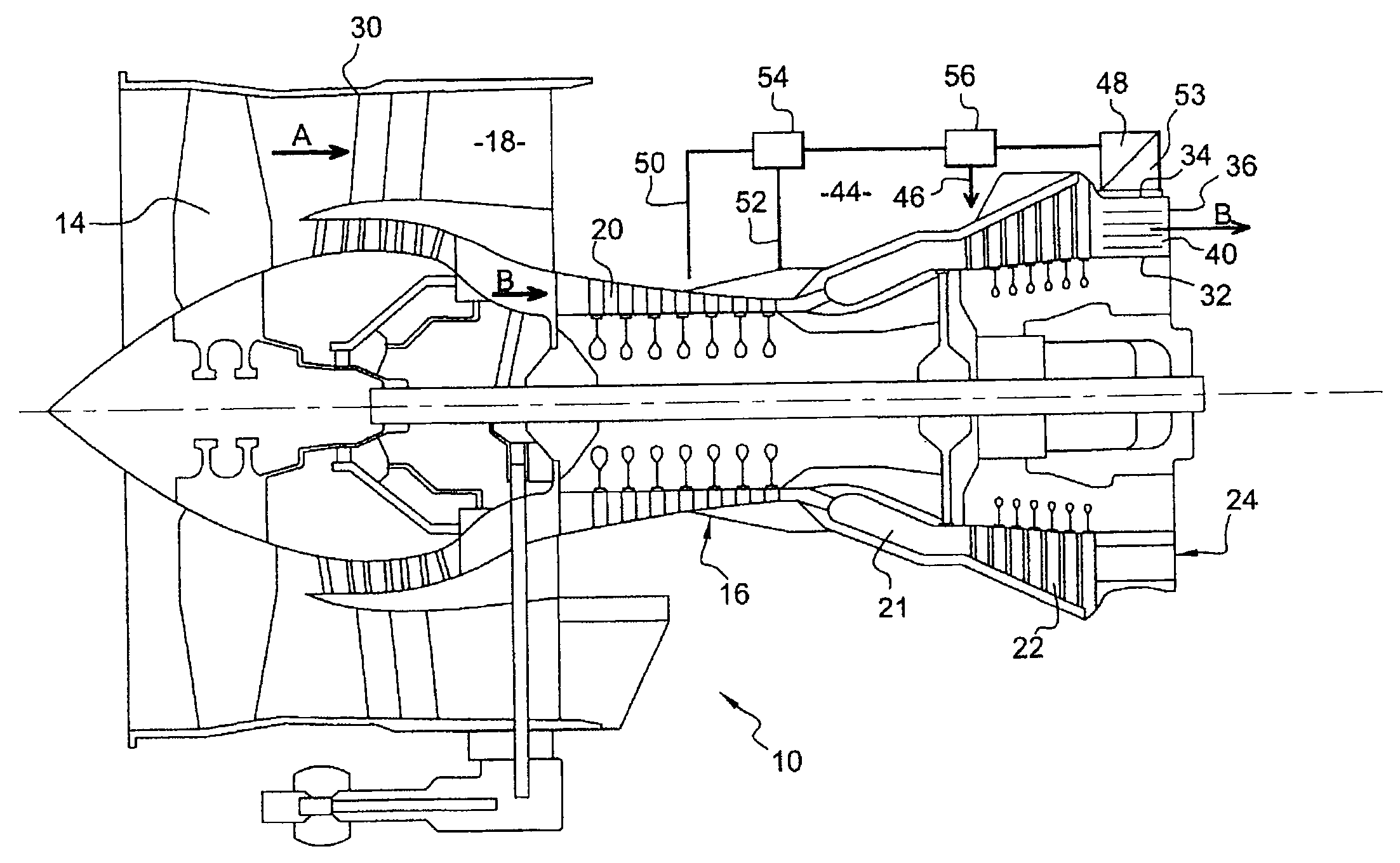
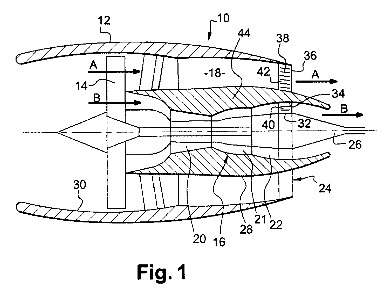
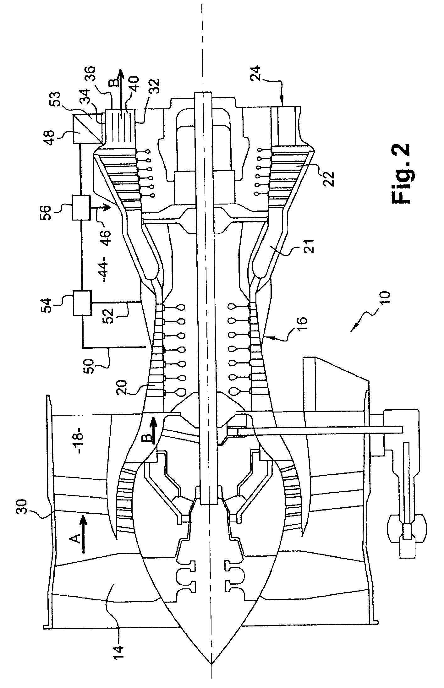
[0020]FIG. 1 represents a dual-flow jet engine 10, comprising a nacelle 12 in which a fan wheel 14 is mounted upstream of an engine body 16 essentially comprising, from upstream to downstream, a compressor 20, a combustion chamber 21, a turbine 22, an exhaust casing 24 and an ejection cone 26.
[0021]The fan wheel 14 is driven rotation-wise by the turbine 22 of the jet engine, in a manner well known to those skilled in the art. While the engine is operating, the fan 14 generates a secondary flow of air A, which flows toward the back around the jet engine in a fan duct 18, and which supplies a part of the thrust of the engine. A portion of the air entering into the engine forms a primary flow B which feeds the inlet compressor 20 of the jet engine, then is mixed with fuel in the fuel chamber 21. The combustion gases leaving the combustion chamber drive the turbine 22 then are ejected between two coaxial walls 32, 34 of the exhaust casing 24 and leave the jet engine flowing along the ej...
PUM
 Abstract
Description
Claims
Application Information
 - R&D
- Intellectual Property
- Life Sciences
- Materials
- Tech Scout
- Unparalleled Data Quality
- Higher Quality Content
- 60% Fewer Hallucinations
Browse by: Latest US Patents, China's latest patents, Technical Efficacy Thesaurus, Application Domain, Technology Topic, Popular Technical Reports.
© 2025 PatSnap. All rights reserved.Legal|Privacy policy|Modern Slavery Act Transparency Statement|Sitemap|About US| Contact US: help@patsnap.com


