

Air inlet system
- Summary
- Abstract
- Description
- Claims
- Application Information
AI Technical Summary
Benefits of technology
Problems solved by technology
Method used
Image

Examples
first embodiment
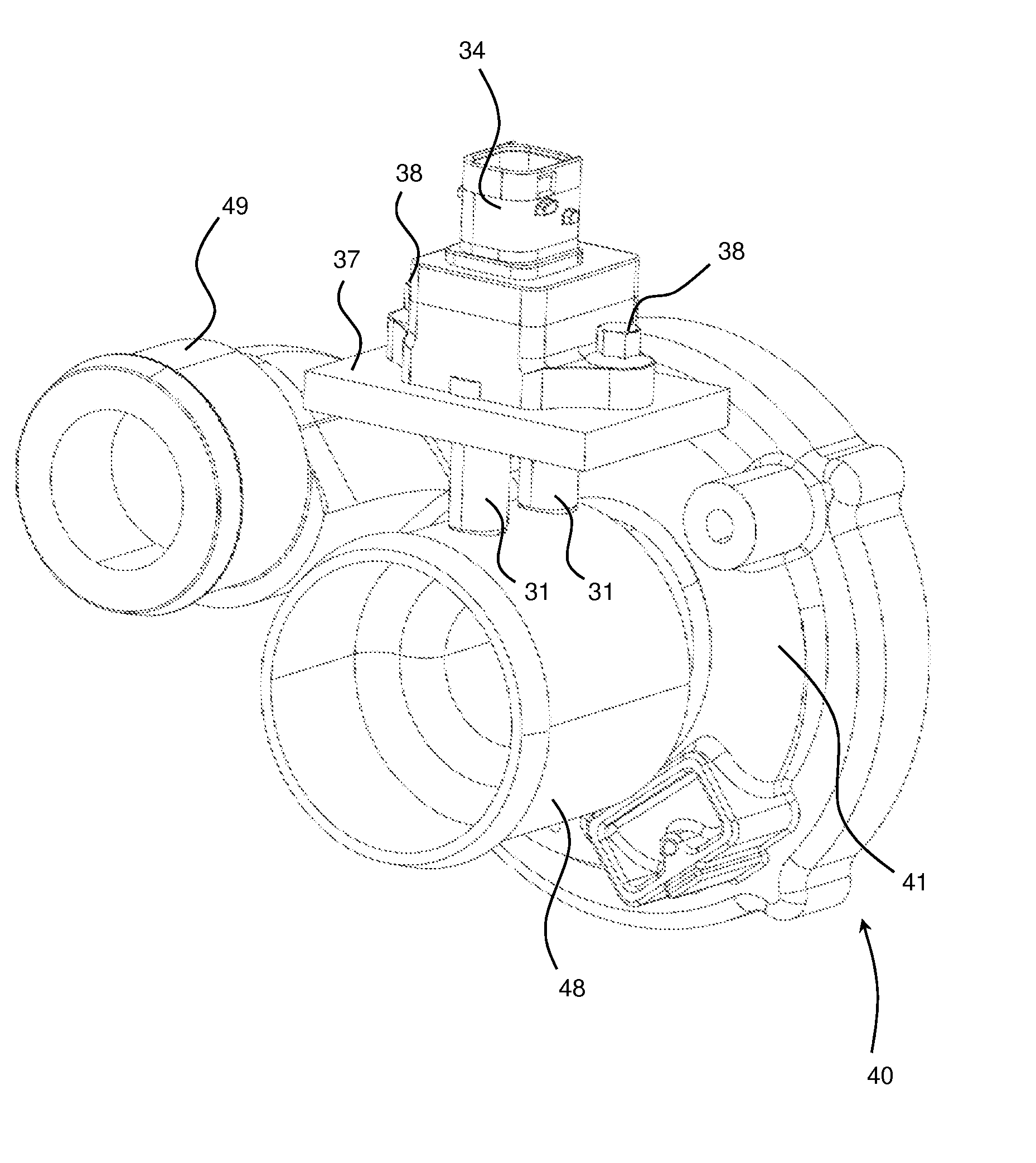
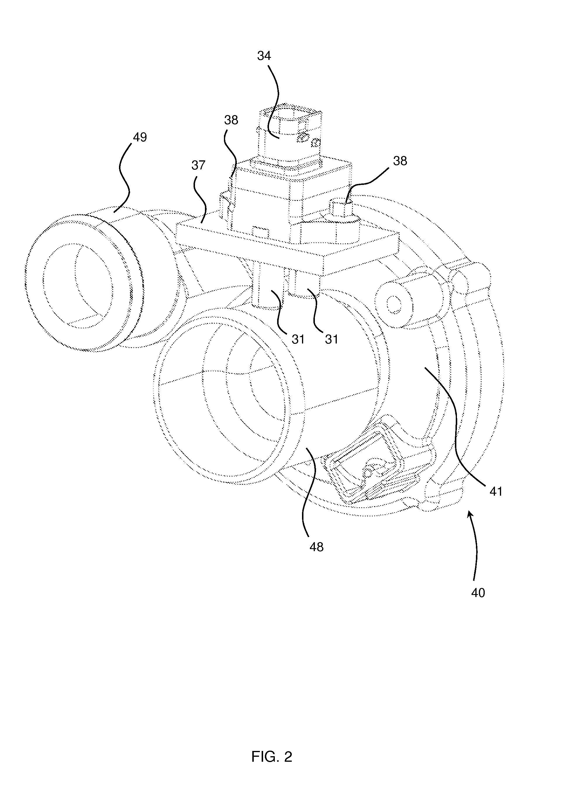
[0093]The throttle 150 comprises a throttle valve 152 rotatable to open and close the throttle by an actuator 153 and a throttle housing 141. The housing 141 comprises an inlet 148 and an outlet 149, where the throttle inlet extends axially upstream from the valve 152 and throttle actuator 153. The throttle inlet 148 comprises a Venturi tube 166 of a similar format to Venturi tube 66 of the first embodiment, and which is formed from the same casting as a portion of the throttle housing, minimising the overall footprint of the overall throttle 150. The throttle 150 is typically mounted to the inlet manifold 62 of the engine. In alternative embodiments, different throttles may be used such as a double barrel or sliding plate throttle.
[0094]The throttle 150 further comprises two bores 132, 133 which extend radially into the Venturi tube 166 through a wall of the inlet 148. However this embodiment differs from the first in that the mounting platform 137 is formed from the same casting a...
third embodiment
[0095]FIGS. 12 to 16 illustrate what can conveniently be described as a “standalone” MAF sensor assembly 230 according to the present invention, corresponding components of this figure are labelled 100 higher with respect to FIGS. 7-11. Only differences are discussed in more detail.
[0096]The standalone MAF sensor 230 is fixed to a downstream end 80 of an air inlet duct 224 via a constant tension hose clip 269. In alternative embodiments, other retention methods suitable for the operating environment may be used. The standalone MAF sensor assembly 230 further comprises a V-band clip 272, through which it can be secured to upstream end of an air flow control component—e.g. to the open end of either a standard turbocharger compressor housing (not shown), a standard throttle (not shown) or a standard intake manifold housing (not shown). In alternative embodiments, different gas tight interfaces suitable for the operating environment may be used. As in the first and second embodiments, t...
PUM
 Abstract
Description
Claims
Application Information