
Method for shot peening and a machine therefor (as amended)

Active Publication Date: 2011-04-28
SINTOKOGIO LTD
View PDF11 Cites 3 Cited by
  • Summary
  • Abstract
  • Description
  • Claims
  • Application Information

AI Technical Summary

Benefits of technology

The objectives of the present invention are to provide a method for shot peening wherein the status of shot materials can be measured while the work is being processed, and to provide a machine for carrying out the method. The work is processed by being hit by the shot materials that are shot by compressed air. The requirements for maintaining and calibrating the sensor that is used for the measurement are reduced because the wear of the sensor is prevented.
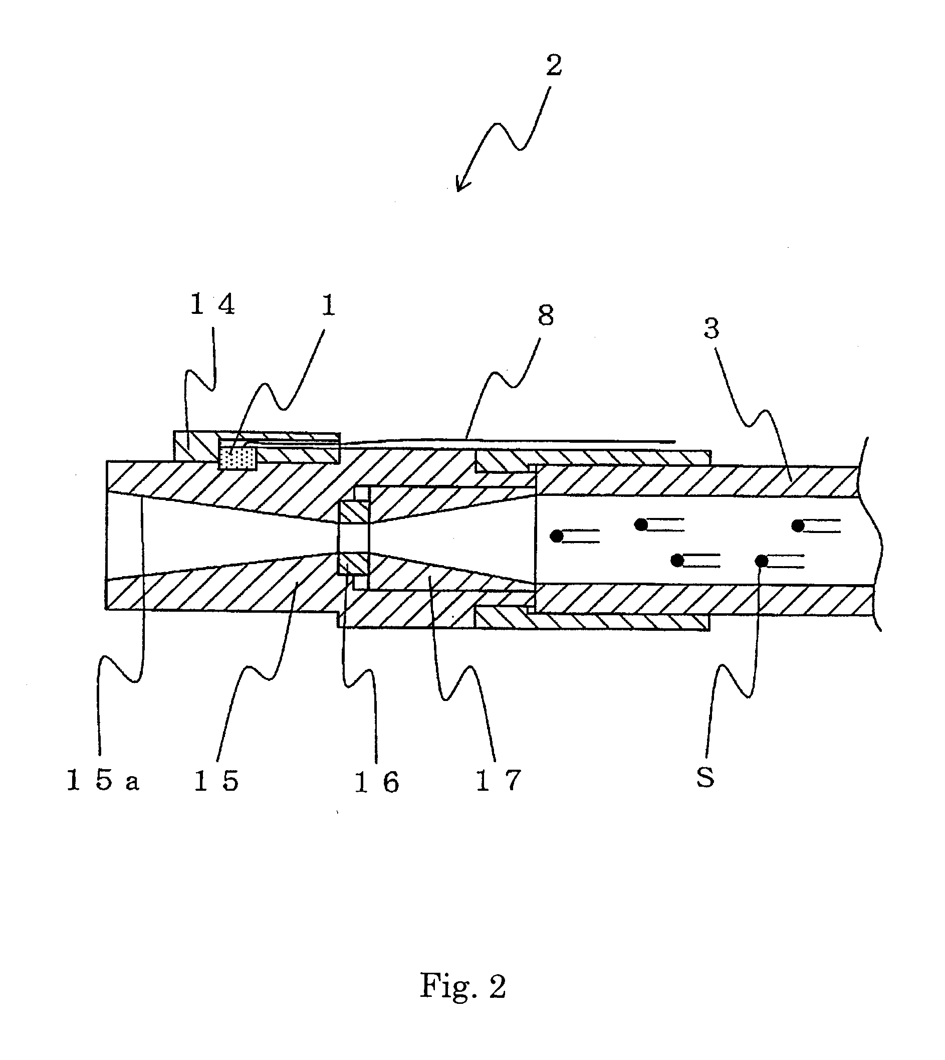
By the present invention, since the transducer that detects elastic waves and transduces them to high-frequency electrical signals is located in the shooting nozzle, the condition of the shot materials can be measured while the work is being processed. Unlike the conventional method and machine, since no materials hit the sensor after being reflected to it, the status of the shot materials can be measured more precisely than in that prior-art method and machine. In addition, since the sensor is not hit by the materials, it can be used for the life of the shooting nozzle. Thus, the requirements for maintenance and calibration are reduced. So, the cost can be reduced.

Problems solved by technology

However, the above-mentioned methods do not detect the actual conditions of the shot materials while they are being shot, since controlling the grain sizes of the shot materials, detecting the rotation of a work, or controlling the pressure for shooting and the amount of materials to be shot, just controls the conditions of the operation.
Thus, no measurement can be done while an actual work is being processed.
In addition, because over time the sensor is worn out by shot peening, its maintenance and calibration may be required.
Further, precise measurements are difficult to make, since the shot materials hit the sensor after they are reflected by it or the work that is being processed.
These points are the problems.

Method used


Image

  • Method for shot peening and a machine therefor (as amended)
  • Method for shot peening and a machine therefor (as amended)
  • Method for shot peening and a machine therefor (as amended)

Examples


Embodiment Construction

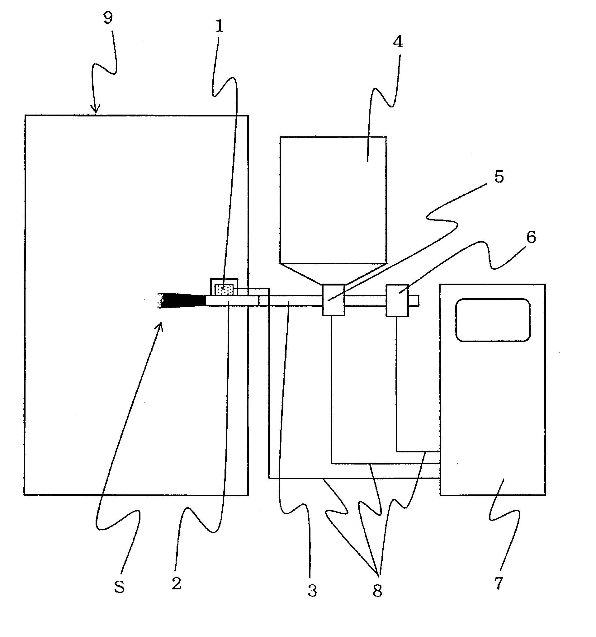
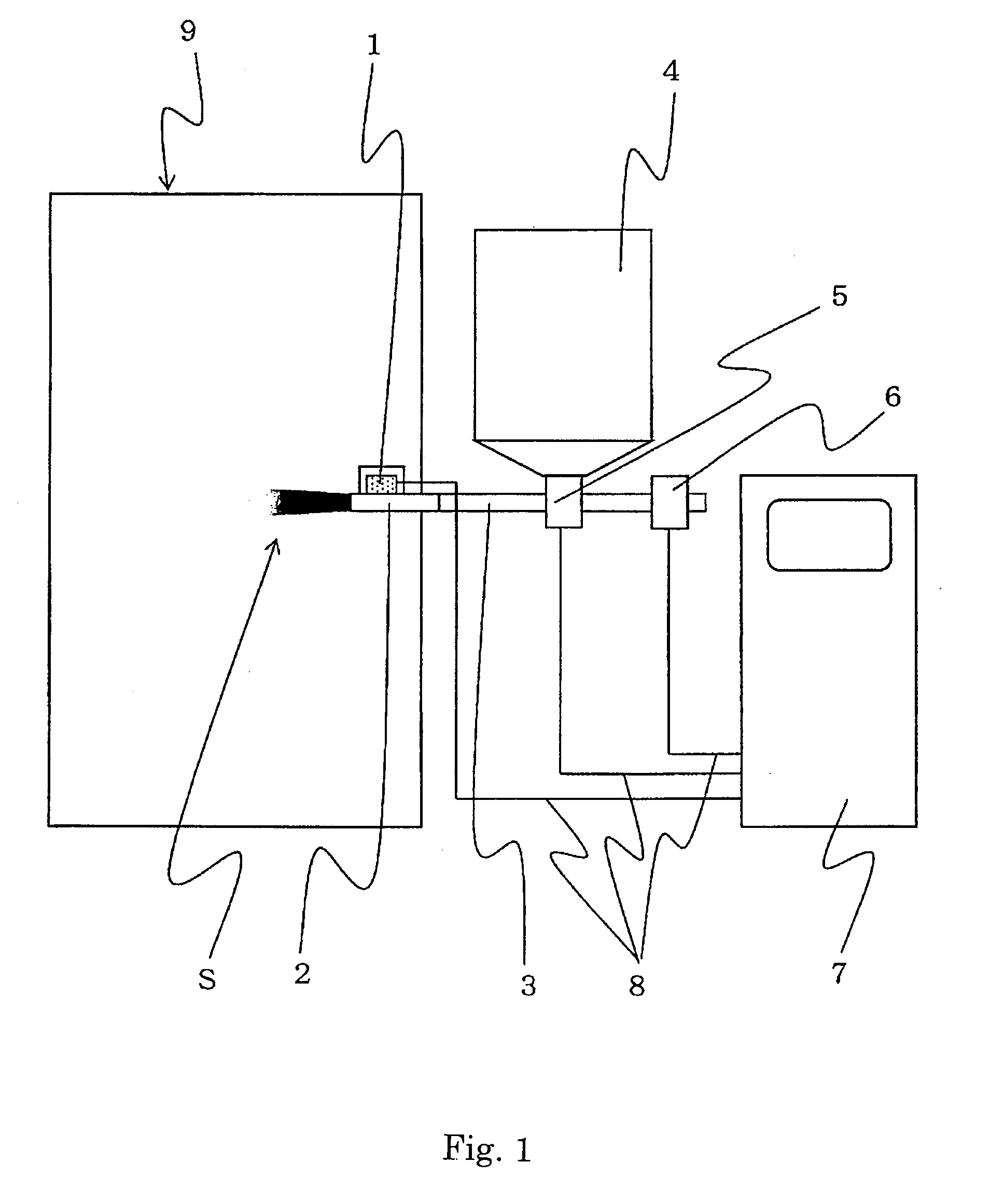
Below, a method for shot peening and the machine for carrying out the method are discussed with reference to the drawings. As shown in FIG. 1, the shot-peening machine of one embodiment of the present invention comprises a storage tank 4 for shot materials, a device 5 for adjusting the amount of the materials to be shot based on the volume flow or mass flow of them, a device 6 for adjusting the pressure of the compressed air to be used for shooting the materials, a shooting nozzle 2 to shoot the materials, an AE sensor (Acoustic Emission sensor) 1 as a transducer, and a controller 7. The shooting nozzle 2 shoots the materials from the device 5 for adjusting the amount of the materials to be shot through a hose 3 as a means for transporting the materials by using the compressed air that is adjusted by the device 6 for adjusting the pressure of the compressed air. The AE sensor 1 detects the elastic waves that are generated by the shot materials that pass through the shooting nozzle 2...


PUM

PropertyMeasurementUnit
Pressureaaaaaaaaaa
Frequencyaaaaaaaaaa
Orderaaaaaaaaaa

Abstract

A method for shot peening wherein the work is processed by being hit by shot materials that are shot by compressed air, and a machine for carrying out the method are provided. By the present invention the status of a work can be measured while the work is being processed. The requirements for maintaining and calibrating the sensor that is used for the measurement are reduced because the wear of the sensor is prevented. The method for shot peening is to process a work by shooting the shot materials with compressed air from a shooting nozzle against the work. The shooting nozzle is equipped with a transducer that detects elastic waves and transduces them to high-frequency electrical signals. The elastic waves are generated when the shot materials pass through the shooting nozzle. The characteristic values of the shot materials, which pass through the shooting nozzle, are measured and monitored based on the signals.

Description

TECHNICAL FIELDThe present invention relates to a method for shot peening and a machine for it. Specifically it relates to a method that comprises the steps of electrically measuring and controlling the conditions of shot materials while they are being shot and a machine for carrying out the method.BACKGROUND ARTSeveral conventional methods for measuring the status of works that are processed by air-type shot-peening machines are known. Methods for controlling the status while the works are being processed include one that comprises the steps of measuring the pressure for shooting and the amount of materials to be shot by means of a pressure sensor, a load cell, or a sensor for sensing the amount of passing metal, and feeding back such measurements. The methods may include the steps of controlling the grain sizes of the shot materials, detecting the rotation of a work, etc. Another method, called the “Almen method,” is known. It employs a specimen to be shot instead of a work and ch...

Claims


Application Information

Patent Timeline
IPC IPC(8): B24C1/10B24C5/02
CPCB24C7/0046B24C1/10
Inventor SUZUKI, HIROAKI
Owner SINTOKOGIO LTD
Learn More