Handrail and railing assembly

a technology of handrails and railings, applied in the direction of fencing, building types, constructions, etc., can solve the problems of time-consuming assembly or replacement, the arm cannot be adjusted according to the height and physical condition of users after welding, and the assembly cannot be done according to user height and physical condition

Active Publication Date: 2018-09-13
KUO CHINGYAO +1
View PDF4 Cites 12 Cited by
  • Summary
  • Abstract
  • Description
  • Claims
  • Application Information

AI Technical Summary

Benefits of technology

[0005]Accordingly, it is a major objective of the present invention to provide a handrail and railing assembly, such that each of the handrails can be installed onto the railings quickly according to site requirements.
[0006]It is another objective of the present invention to provide a handrail and railing assembly, which is assembled by a handrail, a plurality of support frames, a movable corner, and a corner connecting rod; the handrail is constructed by connecting a plurality of handrail units and connecting sleeves, and is able to extend at the corner through angle adjustment by the movable corner. The plurality of support frames provides stable support for the handrail. Overall, the handrail and railing assembly is easy to implement, adjust, and replace.
[0007]It is a further objective of the present invention to provide a handrail and railing assembly, wherein the support frame includes a holder, a U-shaped seat and a bracket. The fixed seat is fixed to the railing post or thin tube; the U-shaped seat is connected to the fixed seat; one end of the bracket can be connected to the U-shaped seat for angle adjustment, and the top of the bracket is connected to the handrail by a screw to provide a stable support for the handrail.

Problems solved by technology

Although the welding method is easy to apply with the advantage of stability, arms cannot be adjusted according to user's height and physical condition after the completion of welding.
Also, assembly or replacement is quite time-consuming, more likely to cause waste, resulting in environmental issues.

Method used


Image

  • Handrail and railing assembly
  • Handrail and railing assembly
  • Handrail and railing assembly

Examples


Embodiment Construction

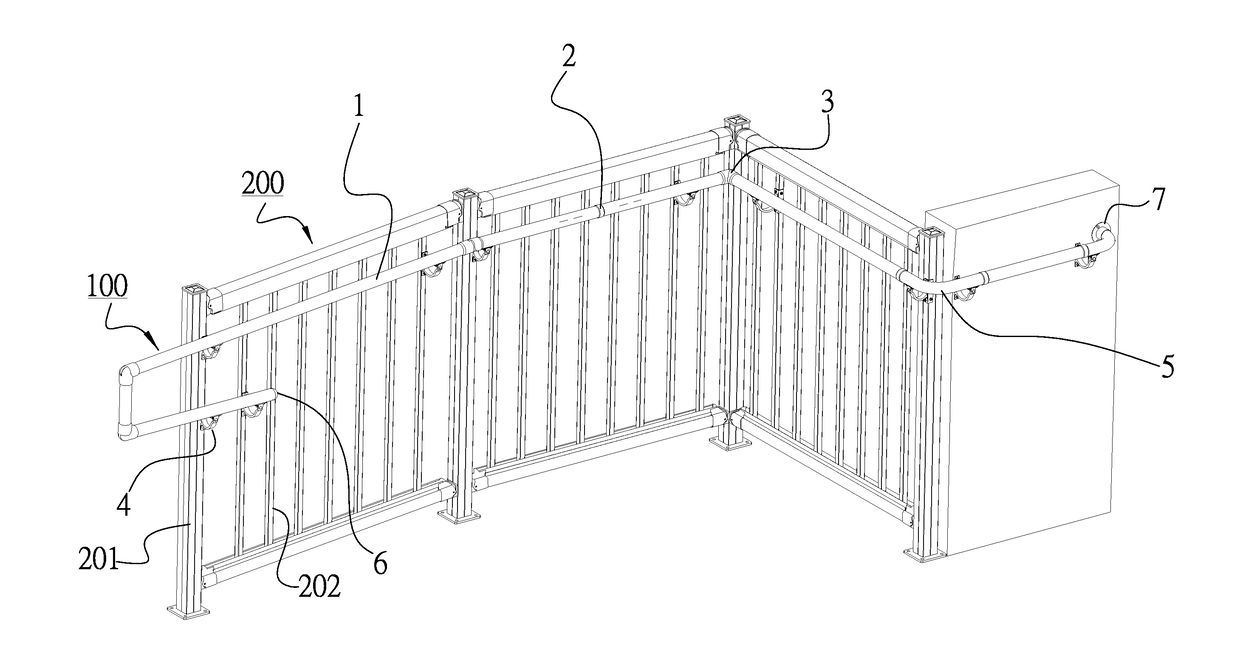
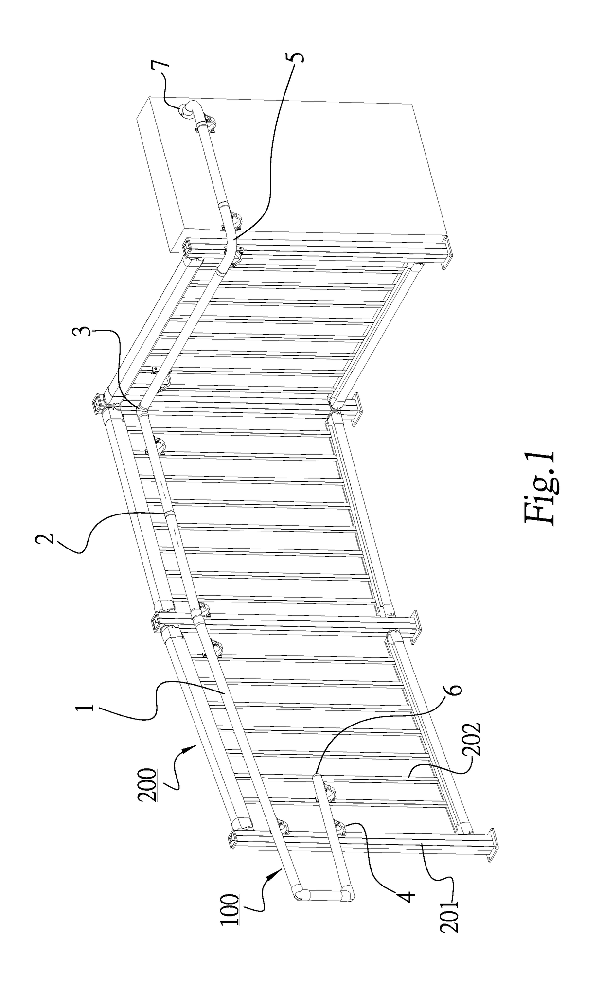
[0022]As shown in FIG. 1, a handrail and railing assembly 100 is fixed to the railing 200 laterally. The handrail and railing assembly 100 includes: a handrail 1, a connecting sleeve 2, a movable corner 3, a support frame 4, and a corner connecting rod 5. The corner connecting rod 5 is installed at the right-angle corner, such that the handrail lean be extended and bent at a 90°.

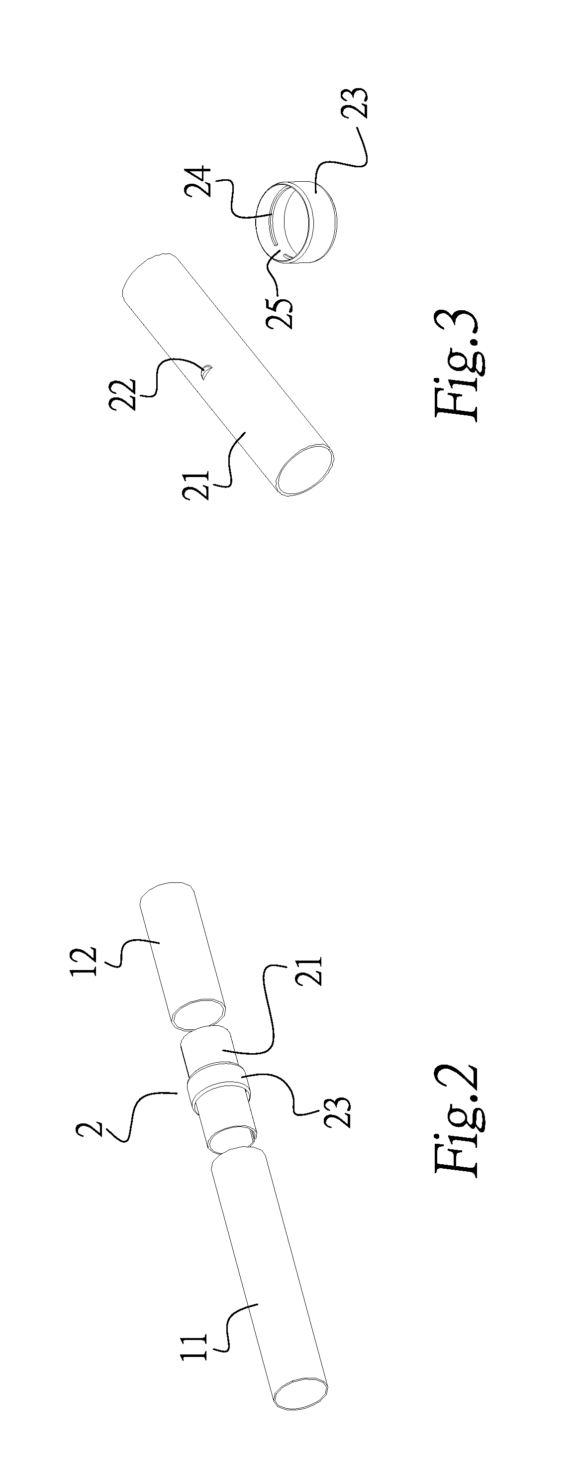
[0023]Please refer to FIGS. 2 and 3. The handrail 1 is constructed by connecting a plurality of handrail units 11, 12 . . . sequentially. Each of the handrail units 11, 12 is connected by a connecting sleeve 2. The connecting sleeve 2 is provided with a sleeve body 21. The outer surface of the sleeve body 21 is provided with a bump 22 as well as a collar 23. A rib 24 is provided inside the collar 23. The rib 24 has a slightly larger gap 25 than the bump 22. Whereby, when the collar 23 is fitted outside the sleeve body 21, the gap 25 on the rib 24 is opposite to that of the bump 22, the collar 23 can slide le...


PUM


Abstract

Disclosed is a handrail and railing assembly, which is made up of a handrail, a plurality of support frames, a movable corner, connecting sleeves and a corner connecting rod; wherein the handrail is connected by a plurality of handrail units and connecting sleeves, and connected by a movable corner or corner connecting rod at a corner; the spaced support frames are provided to hold the handrail. The handrail and railing assembly meets the strength requirements of different sites and can be adjusted according to the on-site installers.

Description

BACKGROUND OF THE INVENTION1. Field of the Invention[0001]The present invention relates to a handrail and railing assembly, particularly to a handrail and railing assembly which can be quickly assembled by a handrail, a movable corner, a corner connecting rod and support frames and adjusted according to on-site environment.2. Description of the Related Art[0002]With the development of civilization and economy, the government and the community have begun to pay more attention to those who are inconvenienced by aging, illness or accident For people with reduced mobility, apart from establishing a sound health care system, there is a need to provide ancillary facilities to facilitate their operation. For example, in general public places, there will be more barrier-free access to persons with reduced mobility through wheelchairs or slow action into / out of the building. The setting of handrails is even more important for people who are slow or physically weak.[0003]Conventional handrail...

Claims


Application Information

Patent Timeline
Patent Type & Authority Applications(United States)
IPC IPC(8): E04F11/18E04H17/14
CPCE04F11/1804E04F2011/1889E04H17/1421E04F11/1808E04F11/1838
Inventor KUO, CHINGYAOLIEFKE, NORMAN WILLIAM
Owner KUO CHINGYAO
Why Eureka
Try Eureka