Sliding member

Active Publication Date: 2018-09-13
DAIDO METAL CO LTD
View PDF11 Cites 3 Cited by
  • Summary
  • Abstract
  • Description
  • Claims
  • Application Information

AI Technical Summary

Benefits of technology

[0004]During a steady operation of an exhaust turbine, a large-scale electrical generator or other devices, a fluid film, such as oil film, is formed between a shaft member and a sliding member. Thus, a direct contact between a surface of the shaft member and a sliding surface of the sliding member is prevented. However, particularly in a state of high-speed rotation of the shaft during the operation, centri

Problems solved by technology

However, particularly in a state of high-speed rotation of the shaft during the operation, centrifugal force effects on the fluid film strongly.
In the case, if the resin composition includes non-oriented or isotropically dispersed fibrous particles as disclosed in JP-A-2013-194204, the resin composition in the vicinity of the slidi

Method used


Image

  • Sliding member
  • Sliding member
  • Sliding member

Examples


Example

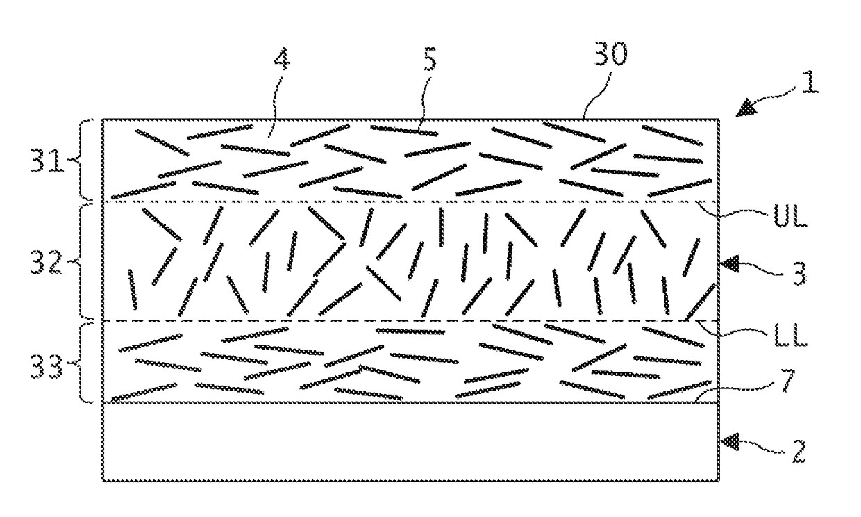
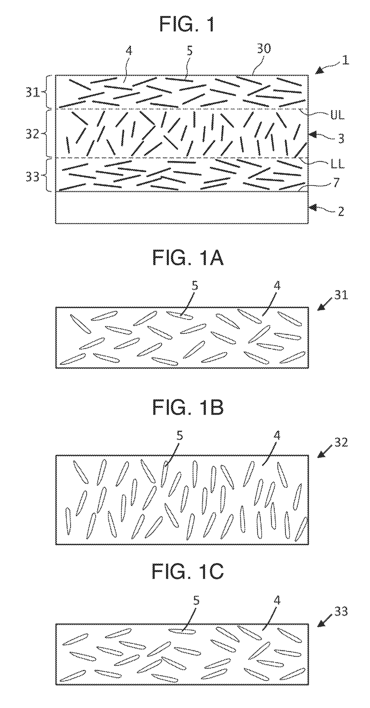
[0107]In Comparative Example 15, on the other hand, the fibrous particles in the sliding layer have the same orientation (orientation in parallel to sliding surface) between the sliding surface side area, the intermediate area, and the interface side area, and thus the cracking and the shearing were easily generated. In the case, the sliding layer was easily worn and an amount of abrasion increased.

Example

[0108]In Comparative Example 11, since the fibrous particles have an average size smaller than 5 μm, it is considered that the effect of increasing the strength (resistance to deformation) of the sliding layer decreased. Thus, cracking on the surface of the sliding layer occurred, leading to increase of abrasion.

Example

[0109]In the sliding layer in Comparative Example 12, since the fibrous particles have a large average size of 29 μm, it is considered that the fibrous particles itself broke by shearing when a load was applied to the sliding layer by a high pressure of the fluid film. Thus, cracking on the surface of the sliding layer was generated, leading to increase of abrasion and shearing was generated at the interface between the sliding layer and the back metal.


PUM

PropertyMeasurementUnit
Lengthaaaaaaaaaa
Fractionaaaaaaaaaa
Fractionaaaaaaaaaa

Abstract

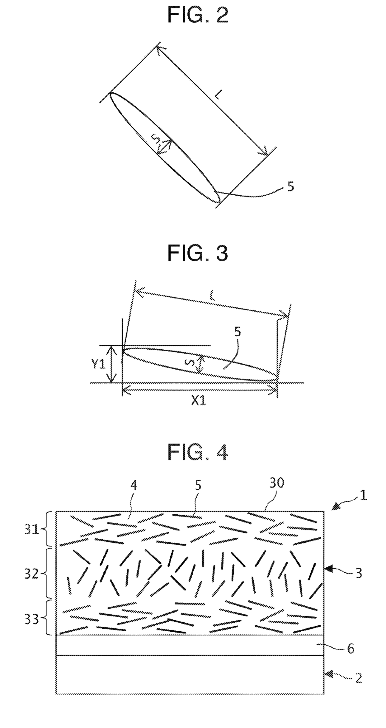
Provided is a partially-annular sliding member including a sliding layer including fibrous particles having an average particle size of 5-25 μm dispersed in a synthetic resin at a volume ratio of 10-35% of the sliding layer. The particles having a major axis length ≤20 μm are included at a volume ratio of ≥10% to total particles. A sliding surface side area is defined from the sliding surface and has a thickness of 25% of a sliding layer thickness T, where the fibrous particles having a major axis length of ≥20 μm have a dispersion index of 1.1-6. An interface side area is defined from the interface and has a thickness of 25% of T, where the dispersion index is 1.1-6. An intermediate area is defined between the both areas, where the dispersion index is 0.1 to less than 1.

Description

BACKGROUND OF THE INVENTIONField of the Invention[0001]The present invention relates to a sliding member for a thrust bearing. Particularly, the invention relates to a sliding member having a partially annular shape and including a back metal layer and a sliding layer including synthetic resin and fibrous particles. The invention further relates to a thrust bearing including the sliding member.Description of the Related Art[0002]A thrust bearing has been used for a rotation shaft of an exhaust turbine, a large-scale electrical generator or other devices. Such thrust bearing includes a plurality of sliding members each having a partially annular bearing pad shape and the sliding members are arranged along a circumferential direction and facing a thrust collar surface of the rotation shaft. In such a tilting pad type thrust bearing, each of the sliding members having the partially annular shape is supported by a pivot in such a manner as to be slightly oscillatable with respect to the...

Claims


Application Information

Patent Timeline
IPC IPC(8): F16C33/12F16C17/00
CPCF16C33/121F16C33/122F16C17/00F16C2208/02F16C2208/20F16C33/201F16C33/206F16C2380/26F16C2208/90F16C2208/86F16C2208/36F16C2208/40F16C2208/42F16C2208/44F16C2208/78F16C2208/54F16C2208/52F16C33/205F16C2208/04F16C17/02F16C33/125F16C33/127Y10T428/249946Y10T428/249942C08J5/042B29C45/0005C08J5/043
Inventor YAMAUCHI, TAKAYOSHI
Owner DAIDO METAL CO LTD
Why Eureka
Try Eureka