
Method for inverse tone mapping of an image with visual effects

Active Publication Date: 2018-09-13
INTERDIGITAL CE PATENT HLDG
View PDF0 Cites 3 Cited by
  • Summary
  • Abstract
  • Description
  • Claims
  • Application Information

AI Technical Summary

Benefits of technology

The patent is about a method for creating high dynamic range (HDR) lighting effects in photography. One aspect of the method involves using a computer to generate imagery components, such as composites or effects, to enhance the image. Another aspect involves using a combination of video coding standards to enable automatic processing of low dynamic range (LDR) images, which can be useful in consumer devices or for lowering production costs. Overall, the method can produce high-quality HDR lighting effects with relatively minimal impact on the final image.

Problems solved by technology

This is particularly problematic for images containing visual effects.
Since parts of LDR images related to VFX reveal significant highlights, dark shadows, saturated colors and generally light effects of high visual quality, the poor quality of VFX in HDR images that were generated by inverse tone mapping methods from LDR images containing VFX is particularly troublesome.
Notably can be expected that parts of such HDR images suffer from clipping, luminance compression, lack of details, modification of saturation, noise amplification and banding.
Although several iTMO solutions exist such as different iTMO depending on parts of the image or iterative ITMO process, none of those methods particularly address the specificity of the images generated with VFX.

Method used


Image

  • Method for inverse tone mapping of an image with visual effects
  • Method for inverse tone mapping of an image with visual effects
  • Method for inverse tone mapping of an image with visual effects

Examples


Embodiment Construction

[0040]In the discussion that follows, specific details of particular embodiments of the present techniques are set forth for purposes of explanation and not for purposes of limitation. It will be appreciated by those skilled in the art that other embodiments may be employed apart from these specific details. Furthermore, in some instances detailed descriptions of well-known methods, interfaces, circuits, and devices are omitted so as not obscure the description with unnecessary detail.

[0041]Those skilled in the art will appreciate that some or all of the functions described may be implemented using hardware circuitry, such as analog and / or discrete logic gates interconnected to perform a specialized function, ASICs, PLAs, etc. Likewise, some or all of the functions may be implemented using software programs and data in conjunction with one or more digital microprocessors or general purpose computers.

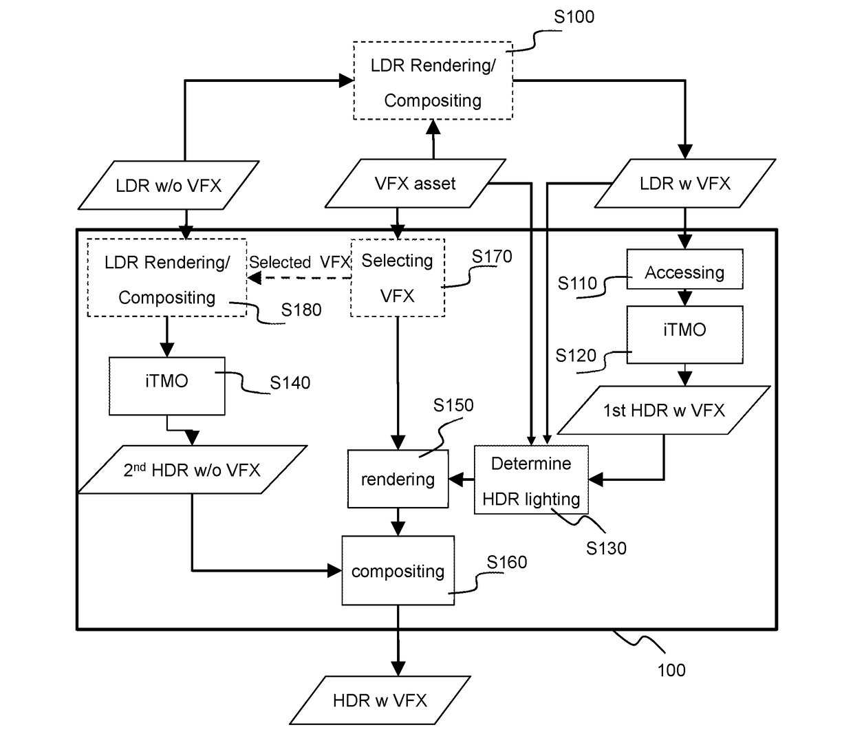
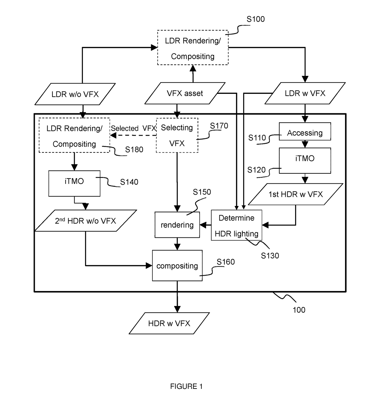
[0042]Now, reference will be made to FIG. 1 for illustrating a method 100 for invers...


PUM


Abstract

A method and apparatus for inverse tone mapping of an LDR image with computer generated imagery components, such components being also called visual effects, are disclosed. The disclosed method includes accessing a first LDR image, the first LDR image being obtained from at least one computer generated imagery component rendered and composited into an LDR reference image or background plate; determining an HDR lighting indication responsive to information extracted from a part of the first LDR image and a respective part of a first intermediate HDR image obtained by applying a first pass inverse tone mapping to the first LDR image; obtaining a second intermediate HDR image by applying a second pass inverse tone mapping to the LDR reference image; obtaining the first HDR image from the computer generated imagery components rendered using HDR lighting indication and composited into the second intermediate HDR image.

Description

REFERENCE TO RELATED EUROPEAN APPLICATION[0001]This application claims priority from European Patent Application No. 17305256.4, entitled “METHOD FOR INVERSE TONE MAPPING OF AN IMAGE WITH VISUAL EFFECTS”, filed on Mar. 9, 2017, the contents of which are hereby incorporated by reference in its entirety.TECHNICAL FIELD[0002]The invention pertains to the field of high dynamic range imaging and addresses notably the problem of inverse tone mapping of low dynamic range content containing visual effects.BACKGROUND ART[0003]This section is intended to introduce the reader to various aspects of art, which may be related to various aspects of the present invention that are described and / or claimed below. This discussion is believed to be helpful in providing the reader with background information to facilitate a better understanding of the various aspects of the present invention. Accordingly, it should be understood that these statements are to be read in this light, and not as admissions o...

Claims


Application Information

Patent Timeline
IPC IPC(8): G06T5/00
CPCG06T5/009G06T2207/20208G06T2207/20008G06T2207/10024G06T5/92G06T15/06G06T15/50H04N19/117H04N19/154H04N19/17H04N19/44H04N19/25H04N19/98G06T5/90H04N9/643G06T5/94
Inventor JOLLY, EMMANUELSTAUDER, JURGENGUERMOUD, HASSANE
Owner INTERDIGITAL CE PATENT HLDG
Learn More