Wireless communication apparatus

a communication apparatus and wireless technology, applied in the direction of network traffic/resource management, vehicle components, location information based services, etc., can solve the problems of collision of two wsa(s) and failure to avoid signals using csma/ca technology

Active Publication Date: 2018-09-13
DENSO CORP
View PDF9 Cites 5 Cited by
  • Summary
  • Abstract
  • Description
  • Claims
  • Application Information

AI Technical Summary

Benefits of technology

[0018]In addition, the collision determiner section determines a collision of a plurality of service start informational items based on not only that a reception error is detected under states where a reception channel is set to a control channel, but also that a service execution informational item has been received. Causes producing a reception error include not only a collision of a plurality of service start informational items but also another one such as a failure of the short-range receiver or s

Problems solved by technology

Even the use of the technology of CSMA/CA thus fails to avoid the collision of signals.
This poses a possibility that

Method used


Image

  • Wireless communication apparatus
  • Wireless communication apparatus
  • Wireless communication apparatus

Examples


first embodiment

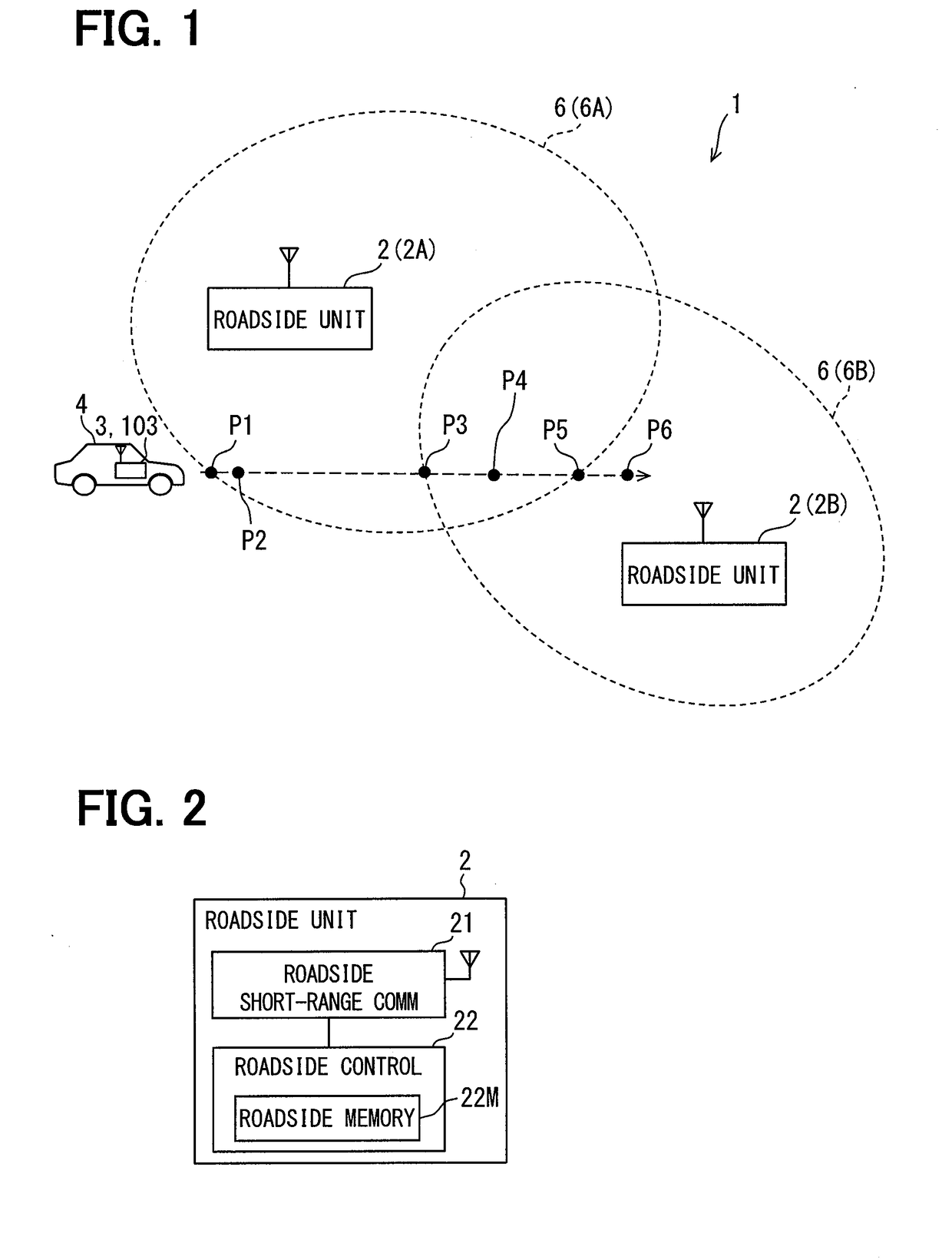
[0037]The following describes embodiments of the present disclosure with reference to drawings. As illustrated in FIG. 1, a wireless communication system 1 according to a first embodiment includes a roadside unit 2 and an in-vehicle unit 3. FIG. 1 also illustrates an in-vehicle unit 103 according to a second embodiment. The in-vehicle units 3 and 103 each are equivalent to a wireless communication apparatus; the roadside unit 2 is equivalent to a service provider station.

[0038][Outline Configuration of Wireless Communication System 1]

[0039]FIG. 1 illustrates two roadside units 2A and 2B; however, the number of roadside units 2 may be equal to or greater than three. When not distinguishing the roadside units 2A and 2B from each other, each is represented as a roadside unit 2. In addition, a single in-vehicle unit 3 mounted in a vehicle 4 (also referred to as a host vehicle 4) is illustrated in FIG. 1; however, it may be any one of a plurality of in-vehicle units 3 individually mounte...

second embodiment

[0106]The following explains a second embodiment. In the explanation of the second embodiment, an element may be assigned with the reference number identical to that of the element explained in the first embodiment, unless otherwise specifically described. When only part of the configuration of the second embodiment is explained, the other part of the configuration may adopt those of the first embodiment previously explained.

[0107]FIG. 10 illustrates a service provision system 101 in a wireless communication system according to a second embodiment. The service provision system 101 includes a roadside unit 102 and a management apparatus 105.

[0108]The roadside unit 102 includes a wide-range communicator 123 in addition to the same configuration as that of the roadside unit 2 according to the first embodiment. The wide-range communicator 123 is connected to a wide range wireless communication network to communicate with other apparatuses connected to the wide range communication networ...

third embodiment

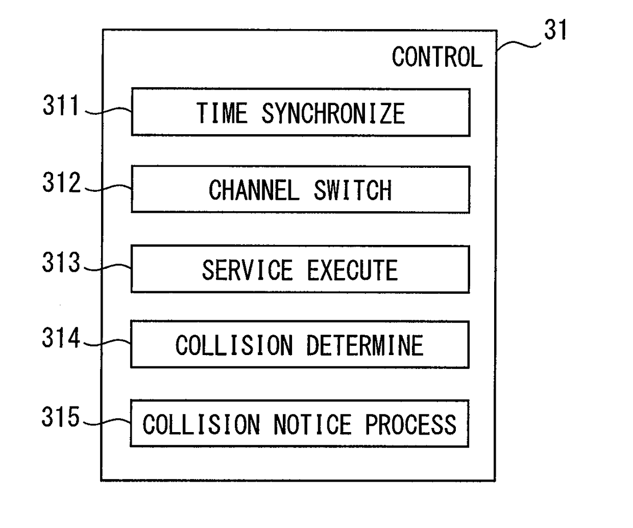
[0145]According to a third embodiment, the in-vehicle unit 203 includes a failure determiner section 316 (also referred to as a failure determiner 316) as illustrated in FIG. 15. The other configuration is the same as that of the in-vehicle unit 3 according to the first embodiment.

[0146]The failure determiner section 316 determines whether the short-range receiver 32A is in a failed state or out of order based on an error ratio (hereinafter, a reception error ratio) of a reception signal which the short-range receiver 32A receives. In detail, the failure determiner section 316 acquires successively the current position which the GNSS receiver 33 calculates, and a travel distance d of the in-vehicle unit 3 successively based on the change in the current positions. Note that the current positions, which are the information for calculating a travel distance d, are equivalent to the travel distance information; the GNSS receiver 33 is equivalent to a travel distance information detector...


PUM


Abstract

A wireless communication apparatus includes: a short-range receiver that designates, as a reception channel, a control channel or one of service channels; a channel switcher section that switches between the control channel and the service channel in designating the reception channel; a collision determiner section that determines presence of service provider stations and a collision of service start informational items transmitted by the respective service provider stations based on (i) that a service execution informational item is received under states where the service channel is designated as the reception channel, and simultaneously (ii) that a reception error is detected under states where the control channel is designated as the reception channel; and a collision notice processor section that transmits a signal collision notice from a predetermined notice transmitter based on that the collision determiner section determines the collision of the service start informational items.

Description

CROSS REFERENCE TO RELATED APPLICATION[0001]The present application is based on Japanese Patent Application No. 2015-187202 filed on Sep. 24, 2015, the disclosure of which is incorporated herein by reference.TECHNICAL FIELD[0002]The present disclosure relates to a wireless communication apparatus and, in particular, to a wireless communication apparatus performing communications via two kinds of channels of a control channel and a service channel.BACKGROUND ART[0003]There is known WAVE (Wireless Access in Vehicular Environments) as a telecommunication standard used for an intelligent transport system as disclosed in Patent literature 1. WAVE uses two kinds of channels of a control channel and a service channel for a vehicular wireless communication apparatus and a roadside unit to communicate with each other.[0004]The service channel is a channel used to transmit or receive the information for executing a service (i.e., service execution information, hereinafter). The service is pro...

Claims


Application Information

Patent Timeline
IPC IPC(8): H04W74/08H04W28/04H04W28/02H04W4/80H04W4/44
CPCH04W74/0816H04W28/04H04W28/0289H04W4/80H04W4/44H04W24/08H04W74/0841H04W4/023H04W72/51
Inventor YAMASHIRO, TAKAHISAKUMABE, SEIGOU
Owner DENSO CORP
Why Eureka
Try Eureka