Mechanical ventilation heat recovery apparatus

a heat recovery apparatus and mechanical ventilation technology, applied in ventilation systems, lighting and heating apparatus, heating types, etc., to achieve the effect of reducing the overall energy consumption of the mvhr system, saving energy, and reducing the heating demand

Active Publication Date: 2018-09-27
BE HIVE TECH LTD
View PDF7 Cites 7 Cited by
  • Summary
  • Abstract
  • Description
  • Claims
  • Application Information

AI Technical Summary

Benefits of technology

[0005]With such an arrangement the inbound and outbound air flows can be reversed upstream of the HRU, and upstream of all other elements of the MVHR system such as filters, fans, etc. so that in operation there is no flow reversal in the majority of the system, and the problems associated with flow reversal described above can be avoided. Moreover, because the system can be controlled so as to choose which port to draw inbound air from (namely that where the ambient air temperature requires the least energy to raise or lower it to the desired temperature inside the building) overall energy usage by the MVHR system is reduced. In summer, relatively cool air from the northerly side of the building can be drawn in, and in winter relatively warm air from the southerly side of the building can be drawn in as inbound air. The invention saves energy due to significant heating and hot water reduction in (mostly) the spring and autumn months when there is still plenty of sun light but the house needs heating in the evening. In winter when the sun comes out it is hoped to reduce the heating demand by the warm air entering and by reducing the amount of time the building's main heat source (which could be any other heat source, such as a gas boiler or an Air Source Heat Pump (ASHP)) needs to run, so that the expected saving in winter should be in the region of 20 to 30%. When the system is used for cooling it will of course reduce the temperature in the house and will also reduce the energy demand if there were some sort of active cooling system in the property, but if there is no such cooling system it provides a method of reducing the internal temperature (and has no saving as such indirectly of energy). Conveniently, where the building has a roof with at least two pitched slopes facing in different directions, the first and second ports may be located in these two slopes. The location of the ports under a pitched roof means that much of the ducting for the air flows to and from the ports can be accommodated in the unused eaves space within the roof. Additionally or alternatively, the first and second ports may be located in the outer walls on different sides of the building.
[0006]In practice, few buildings are orientated precisely North-South, but with most pitched roofs or outer walls it will be possible to identify one pitched slope which is more northerly facing and another which is more southerly facing, and the ports would normally be located on these surfaces so as to optimise the energy saving potential. It may be advantageous (and possible) to locate the ports on pitched slopes or walls which face in opposite directions.
[0007]The flow diverter is preferably adapted to switch the flows of ambient and building air between the first and second states simultaneously. A simultaneous flow change upstream of the HRU and of the remainder of the MVHR system means that there is no pressure change in the system downstream of the flow diverter which might dislodge dust or other undesirable particles and introduce them into the air flowing into the building, and also minimises noise because the flow diverter can “balance” the instantaneous changes as it operates. The flow diverter may incorporate a separate plenum for each flow of air, into and out of the building, to flow through; these plenums acts advantageously as noise attenuators, and can also act as “traps” to supplement any filters for trapping unwanted particles in the inbound air.
[0008]The flow diverter may comprise a generally airtight and cylindrical drum having four ports for air to flow through located on at least one end face of the drum, the drum containing a rotatable vane, the ports being disposed such that rotation of the vane within the drum switches air flows between the first and second states, or vice versa. This simple arrangement, which is described further below, is simple and inexpensive to manufacture. Moreover, rotary movement of the vane can be in the horizontal plane (i.e. about an essentially vertical axis), which allows the vane to be balanced and minimises the power required to turn it.

Problems solved by technology

When the system is used for cooling it will of course reduce the temperature in the house and will also reduce the energy demand if there were some sort of active cooling system in the property, but if there is no such cooling system it provides a method of reducing the internal temperature (and has no saving as such indirectly of energy).

Method used


Image

  • Mechanical ventilation heat recovery apparatus
  • Mechanical ventilation heat recovery apparatus
  • Mechanical ventilation heat recovery apparatus

Examples


Embodiment Construction

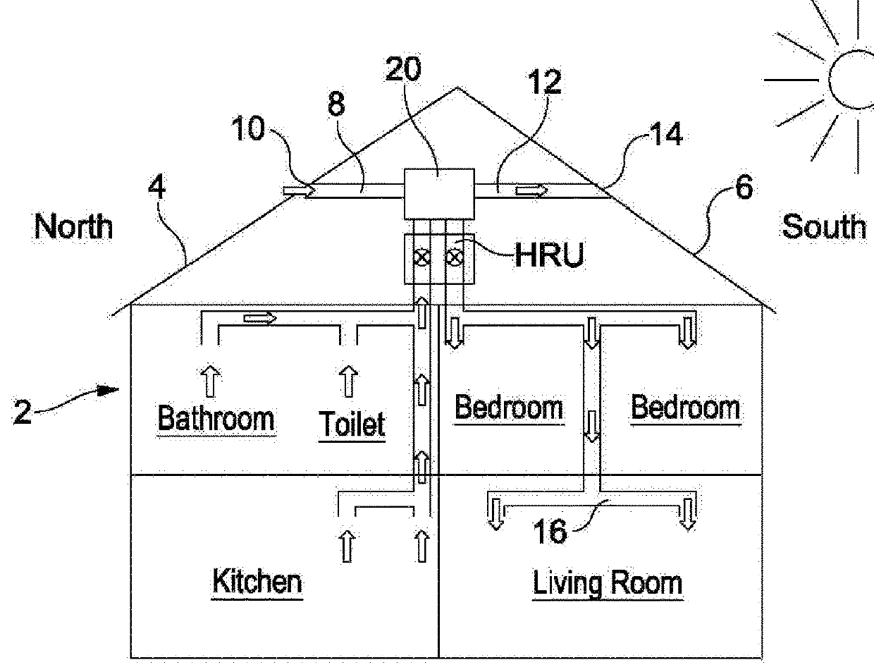
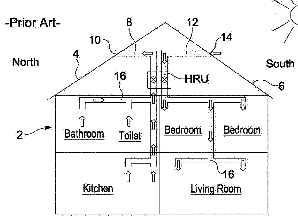
[0024]FIG. 1 shows a domestic house 2 equipped with a typical MVHR system; the house has a pitched roof having two pitched slopes, one slope 4 on a northerly facing side of the house and a second slope 6 on the opposite, southerly facing side of the house. The MVHR system comprises a Heat Recovery Unit HRU which is connected by air flow ducting 8 to a port 10 on the north slope 4 of the roof, and by air flow ducting 12 to a port 14 on the south slope 4 of the roof. Arrows in the drawing show the air flows within the MVHR system. The HRU is provided with fans to draw warm, humid air from the kitchen, bathroom and toilet in the house and to exhaust this outbound air through conduit 8 and port 10 out of the house. Air passageways or ducts 16 are provided to direct the flows of air inside the house. Fans in the HRU also draw fresh, ambient air (inbound air) from outside the house, through port 14 and conduit 12 and into the bedrooms and living room in the house. The HRU also includes he...


PUM


Abstract

A Mechanical Ventilation Heat Recovery (MVHR) system for a building having a roof with at least two pitched slopes facing in different directions, the MVHR system comprising a Heat Recovery Unit (HRU) for receiving and exchanging heat between a flow of ambient air from outside the building and a flow of building air from within the building, the HRU being connected by fluid flow conduits to first and second ports located on different pitched slopes, in which a flow diverter is provided in the conduits between the HRU and the ports, the flow diverter being switchable between a first state in which ambient air flows from the first port to the HRU and into the building and building air flows from the HRU to the second port to be exhausted from the building, and a second state in which ambient air flows from the second port to the HRU and into the building and building air flows from the HRU to the first port to be exhausted from the building. The system can be combined with photovoltaic solar cells and/or an air source heat pump and/or a ground source heat pump system.

Description

FIELD OF THE INVENTION[0001]The present invention relates to Mechanical Ventilation Heat Recovery (MVHR) system for buildings, particularly but not exclusively domestic buildings.BACKGROUND ART[0002]In the search for improvements in the efficiency of buildings such as by increased thermal insulation and weatherstripping (the process of sealing openings such as doors, windows, and trunks from the elements), modern buildings have become more airtight and less well ventilated and thus require some form of energy-effective ventilation system. MVHR systems are energy recovery ventilation systems which use an air-to-air heat exchanger, or Heat Recovery Unit (HRU) which causes the inbound air flowing into the building to exchange heat with the outbound air flowing out of the building, thus providing fresh air inside the building whilst also saving energy by reducing the heating (or cooling) requirement for the inbound air necessary for the interior of the building to be maintained at a com...

Claims


Application Information

Patent Timeline
Patent Type & Authority Applications(United States)
IPC IPC(8): F24F12/00F24F11/79F24F13/10
CPCF24F12/003F24F11/79F24F13/10F24F2012/007F24F2005/0067F24F2005/0057F24F2110/12F24F5/0046F24F12/006F24F2011/0006Y02B10/40Y02B10/20Y02A30/272Y02B30/56F24F12/001
Inventor WOODS, GARRY
Owner BE HIVE TECH LTD
Why Eureka
Try Eureka