Unmanned Aerial Vehicle Control Techniques

a technology for unmanned aerial vehicles and control techniques, applied in process control, using reradiation, instruments, etc., can solve the problems of limited missions that may be performed by uavs, extended visual line of sight operations can involve significant risks, and achieve the effect of minimal separation

Inactive Publication Date: 2018-09-27
COMMONWEALTH SCI & IND RES ORG
View PDF0 Cites 66 Cited by
  • Summary
  • Abstract
  • Description
  • Claims
  • Application Information

AI Technical Summary

Benefits of technology

[0156]b) the flight control module causes the vehicle to maintain at least a minimum separation from the terrain based on the range signal.
[0157]Typically the terrain following orientation points the radar sensor in an angled direction that is rotated downwardly from a forward direction relative to the vehicle, to thereby allow the radar sensor to detect the terrain ahead of the vehicle and any object in a flight direction of the vehicle.

Problems solved by technology

However, aviation safety concerns have led to extensive regulation of UAV operations.
However, this can greatly limit the types of missions that may be performed by UAVs.
However, extended visual line of sight operations can involve significant risks due to the increased likelihood of human error or a breakdown in communications.

Method used


Image

  • Unmanned Aerial Vehicle Control Techniques
  • Unmanned Aerial Vehicle Control Techniques
  • Unmanned Aerial Vehicle Control Techniques

Examples


Embodiment Construction

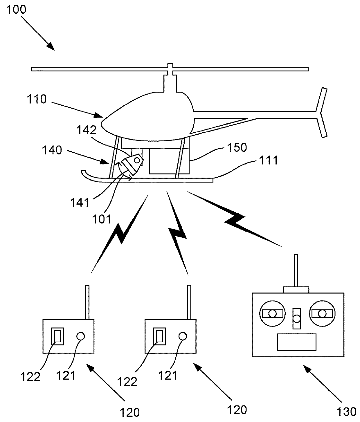
[0194]Examples of methods for controlling the operation of unmanned aerial vehicles will now be described. These examples will be described in the context of an example unmanned aerial vehicle system 100 as shown in FIG. 1.

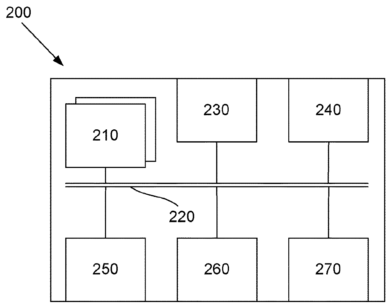
[0195]The system 100 includes an unmanned aerial vehicle 110, typically in the form of an aircraft such as a rotary wing aircraft or fixed wing aircraft that is capable of self-powered flight. In this case, the vehicle 110 is a single rotor helicopter although it will be appreciated that other vehicles 110 may include dual rotor helicopters, quadrotor drones, aeroplanes, or the like. The vehicle 110 will typically be capable of fully autonomous flight and will typically include a flight computer 200 as shown in FIG. 2, which includes one or more processing systems 210 configured to interface with components of the vehicle 110 such as sensors and actuators along with other elements of the system 100, and control the flight of the vehicle 110 accordingly.

[0196]The s...


PUM


Abstract

A method of controlling an unmanned aerial vehicle executing a mission in a defined mission area including a first observation area within a Visual Line of Sight (VLOS) of a First Observer (FO), a second observation area within a VLOS of a second observer (SO), and a transition area within the VLOS of both the FO and the SO, the method including: the vehicle moving into the transition area after completing part of the mission within the first observation area, in sight of the FO; and in response to the vehicle moving into the transition area, determining whether the vehicle is in sight of the SO. The vehicle is including multiple processing systems in wireless communication with multiple remote user interfaces and a radar sensor mounted on the vehicle using a moveable mount for moving the radar sensor between different radar orientations, the radar sensor generating a range signal.

Description

BACKGROUND OF THE INVENTION[0001]This invention relates to techniques for controlling an unmanned aerial vehicle, being particularly suitable for use during extended visual line of sight operations.DESCRIPTION OF THE PRIOR ART[0002]Remotely piloted aircraft and unmanned aerial vehicles (UAVs) are increasingly being adopted across a variety of civil and military applications. However, aviation safety concerns have led to extensive regulation of UAV operations. This has held back widespread proliferation of UAVs, especially for operations near populated areas or other air traffic.[0003]Aviation safety authorities often require that UAVs can only be operated if the vehicle remains within the visual line of sight of a remote pilot, so that the pilot is ready to take action to ensure safe operation of the vehicle and avoid collisions with other air traffic. However, this can greatly limit the types of missions that may be performed by UAVs.[0004]In some jurisdictions, extended visual lin...

Claims


Application Information

Patent Timeline
Patent Type & Authority Applications(United States)
IPC IPC(8): G05D1/00G05D1/10G08G5/00G08G5/04G01S13/88G01S13/94G01S13/93B64C39/02G01S13/933G01S13/935
CPCG05D1/0077G05D1/0016G05D1/0033G05D1/0061G05D1/101G08G5/0013G08G5/0039G08G5/0069G08G5/006G08G5/045G08G5/0086G01S13/882G01S13/94G01S13/9303B64C39/024B64C2201/146G01S13/00G08G5/0082G05D1/106G01S13/935G01S13/933B64U2201/20
Inventor MERZ, TORSTENKENDOUL, FARIDHRABAR, STEFAN
Owner COMMONWEALTH SCI & IND RES ORG
Why Eureka
Try Eureka