Channel state information measurement method and user equipment

a channel state and information measurement technology, applied in the field of mobile communication techniques, can solve the problems of inability to ensure the quality of service (qos) of lte transmission, and inability to ensure the quality of service of lte transmission, so as to increase the efficiency of the whole network

Active Publication Date: 2018-09-27
SAMSUNG ELECTRONICS CO LTD
View PDF13 Cites 27 Cited by
  • Summary
  • Abstract
  • Description
  • Claims
  • Application Information

AI Technical Summary

Benefits of technology

[0013]Embodiments of the present disclosure provide a channel state information measurement method and user equipment, so as to reflect the channel quality when the UE is scheduled on the unlicensed band more accurately, and realize effective scheduling for the base station, thereby increasing efficiency of a whole network.
[0070]It can be seen from the above technical solution that, in the CSI measurement method and UE provided by the present disclosure, the UE receives the resource indication information for performing CSI measurement, performs CSI measurement according to the resource indication information and transmits a CQI report to the control node. In particular, through configuring the CQI report or the CSI measurement in advance, or through the determination on the valid downlink subframe and the carrier occupation situation of the control node on the unlicensed band, it is possible to perform the CSI measurement or report the measurement result respectively with respect to the situation that the control node occupies or not occupy the carrier on the unlicensed band. As such, the reported CQI may reflect the channel quality when the LTE-U base station schedules the UE more accurately, users may be scheduled by the base station more effectively and the efficiency of the whole network is increased.

Problems solved by technology

Contradictions between the booming of the wireless service requirements of users and the limited spectrum resources become increasingly sharp.
Thus, on the unlicensed band, the interference level is not fixed, which makes it hard to ensure the Quality of Service (QoS) of the LTE transmission.
On the unlicensed band, it is a key problem that how to avoid interference between the LTE-U system and the other wireless system such as radar or WiFi.

Method used


Image

  • Channel state information measurement method and user equipment
  • Channel state information measurement method and user equipment
  • Channel state information measurement method and user equipment

Examples


embodiment 1

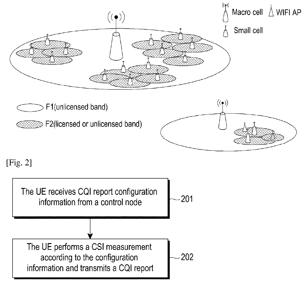
[0086]This embodiment provides a CSI measurement method. A CQI report of the UE is configured in advance, to indicate the UE respectively report CQI on the unlicensed band when the control node occupies or does not occupy the carrier on the licensed band or when another system occupies the carrier on the unlicensed band. The CSI may consist of Channel Quality Indicator (CQI), Precoding Matrix Indicator (PMI), Precoding Type Indicator (PTI), and Rank Indication (RI). The content of CSI depends on the configured feedback mode. For example, the CSI may only consist of CQI. Or, CSI may consist of CQI / PMI / RI wherein the CQI is calculated based on the PMI / RI, i.e., CQI / PMI / RI is measured according to the same set of reference signal. Hereinafter, the content of the CSI is referred to as CQI report for facilitating the description. The method provided by the present embodiment includes the following.

[0087]The UE receives CQI report configuration information from a control node; wherein the...

embodiment 2

[0114]This embodiment provides a CSI measurement method, which configures the CSI measurement resource for the UE by high layer signaling, and indicates the UE to perform CSI measurement on designated measurement resource by physical layer signaling. The method provided by this embodiment includes the following.

[0115]The UE receives CSI measurement configuration information from a control node, wherein the CSI measurement configuration information includes channel measurement and / or interference measurement resource configuration information used for indicating aperiodic channel measurement and / or interference measurement resource; and

[0116]the UE performs a CSI measurement on corresponding channel measurement and / or interference measurement resource in a corresponding subframe indicated by CSI measurement configuration information, and transmits a CQI report to the control node.

[0117]FIG. 4 is a flowchart illustrating a CSI measurement method on the unlicensed band according to an ...

embodiment 3

[0130]This embodiment provides a CSI measurement method, in which the carrier occupation situation of the control node on the unlicensed band is detected by UE, and CSI measurement is performed based on the carrier occupation situation without additional signaling to indicate the CSI measurement resource.

[0131]FIG. 5 is a flowchart illustrating a CSI measurement method on the unlicensed carrier according to an embodiment of the present disclosure. The method includes the following.

[0132]At block 501, the UE detects a carrier occupation situation on an unlicensed band.

[0133]The UE detects whether a serving base station occupies a carrier on the unlicensed band. The UE may detect whether the base station occupies channel in the nth subframe via various manners. For example, the base station may transmit explicit signaling to the UE to indicate whether the base station occupies the channel, and / or indicate a channel occupancy duration. For another example, the base station may transmit...


PUM


Abstract

The present disclosure relates to a pre-5th-Generation (5G) or 5G communication system to be provided for supporting higher data rates Beyond 4th-Generation (4G) communication system such as Long Term Evolution (LTE). Embodiments of the present disclosure provide a channel state information measurement method, including: receiving, by a user equipment (UE), resource indication information for a CSI measurement; performing, by the UE, the CSI measurement according to the resource indication information, and transmitting a Channel Quality Indicator (CQI) report to a control node. According to the present disclosure, users may be scheduled by the base station more effectively and the efficiency of the whole network may be increased.

Description

TECHNICAL FIELD[0001]The present disclosure relates to mobile communication techniques, and more particularly, to a channel state information measurement method and user equipment.BACKGROUND ART[0002]To meet the demand for wireless data traffic having increased since deployment of 4G (4th-Generation) communication systems, efforts have been made to develop an improved 5G (5th-Generation) or pre-5G communication system. Therefore, the 5G or pre-5G communication system is also called a ‘Beyond 4G Network’ or a ‘Post LTE System’.[0003]The 5G communication system is considered to be implemented in higher frequency (mmWave) bands, e.g., 60 GHz bands, so as to accomplish higher data rates. To decrease propagation loss of the radio waves and increase the transmission distance, the beamforming, massive multiple-input multiple-output (MIMO), Full Dimensional MIMO (FD-MIMO), array antenna, an analog beam forming, large scale antenna techniques are discussed in 5G communication systems.[0004]I...

Claims


Application Information

Patent Timeline
Patent Type & Authority Applications(United States)
IPC IPC(8): H04W24/10H04L5/00H04W72/04H04W72/08
CPCH04W24/10H04L5/0057H04W72/0446H04W72/085H04W72/042H04L1/00H04L5/001H04L5/0032H04L5/0048H04L5/006H04L5/0091H04L5/0098H04L5/0073H04L1/0027H04L1/0026H04L5/0092H04W16/14H04W72/23H04W72/542
Inventor LI, YINGYANGWANG, YI
Owner SAMSUNG ELECTRONICS CO LTD
Why Eureka
Try Eureka