Roller and production method for thermoplastic resin film roll

Inactive Publication Date: 2018-10-04
TORAY IND INC
View PDF3 Cites 0 Cited by
  • Summary
  • Abstract
  • Description
  • Claims
  • Application Information

AI Technical Summary

Benefits of technology

The invention involves using a special nip roller with a layer of heat-resisting rubber and abrasion-resisting amorphous carbon coat to improve the quality of film heating processes. This helps to reduce abrasion of the nip roller and prevents defects caused by abrasion powder, resulting in a long period of use for the nip roller and improved quality of the film.

Problems solved by technology

However, the proposals made in Patent Document 2, while being able to reduce the load by the film edge portions to some extent, do not successfully make considerable improvement on abrasion because of insufficient abrasion strength of the rubber in connection with the deformation caused by high pressure load and draw tension during drawing.
Furthermore, the proposals by Patent Documents 3 and 4 are made for a nip roller that is used in a wind-up apparatus for a film at normal temperature, and the documents do not disclose a method for coating a nip roller surface that is used in a heating process of the aforementioned embossing, a longitudinal drawing process, etc.

Method used


Image

  • Roller and production method for thermoplastic resin film roll
  • Roller and production method for thermoplastic resin film roll
  • Roller and production method for thermoplastic resin film roll

Examples


example 1

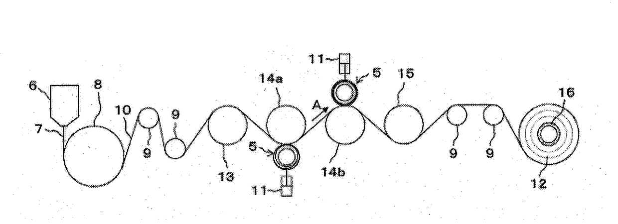
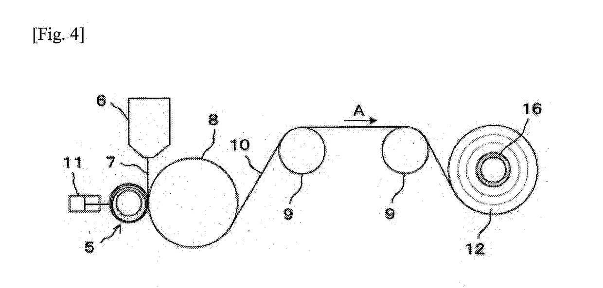
[0039]Using a production apparatus for a film roll illustrated in FIG. 1, polyethylene terephthalate resin was melted by an extruder and discharged from the die 6 while being metered by a gear pump, so as to form a sheet-shaped molten resin 7, which was rapidly cooled by the cooling drum 8 whose temperature was adjusted so that the film temperature was 35° C. Thus, the resin was formed as a film 10 having a width of 2200 mm and an average thickness of 400 μm. The cooling drum 8 was set at a rotation speed of 90 m / min. The pre-heating roller 13, the drawing roller 14, and the cooling roller 15 were rollers through which a heat medium was passed. The obtained film 10 was heated by the pre-heating roller 13 and the drawing roller 14 so that the temperature of the film surface was 130° C. After that, the film 10 was cooled by the cooling roller 15 so that the temperature of the film surface was 35° C. The pre-heating roller 13, the drawing roller 14, and the cooling roller 15 are each a...

example 2

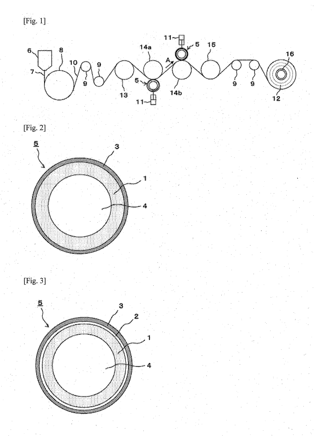
[0041]As the nip roller 5, a roller illustrated in FIG. 3 was used, and the rubber layer 3 thereof had a thickness of 10 mm and was of a hydrogenated nitrile rubber having a hardness of 70°. As for the hydrogenated nitrile rubber, the change in hardness in a heat aging test at 150° C. for 72 hours according to JIS K6257:2010 was 10 degrees, which is less than or equal to 15 degrees, in the type A durometer hardness according to JIS K6253:2012. Furthermore, the hydrogenated nitrile rubber having carbon-carbon double bonds in its main chain was subjected to a halogenation treatment to form a hydrocarbon-based hydrophobic layer 2. Then, the surface of the hydrocarbon-based hydrophobic layer 2 was provided with a DLC layer having a coat thickness of 1 μm as an amorphous carbon coat 3, so as to secure a sticking force. The other conditions were substantially the same as in Example 1.

example 3

[0042]As for the nip roller 5, a roller surface as in Example 2 was subjected to the cutting of rubber of the roller surface so that the diameter becomes smaller toward the roller ends, that is, so as to form conical shapes that extend from taper start points that are locations that are 150 mm inward from the end edges of the roller surface, at 1.5° from a cylinder horizontal surface of the roller in the axis direction of the roller surface parallel to the center rotation axis of the roller to an axis center side. The other conditions were substantially the same as in Example 1.


PUM

PropertyMeasurementUnit
Temperatureaaaaaaaaaa
Timeaaaaaaaaaa

Abstract

This invention provides a nip roller that has heat resistance and abrasion resistance, wherein a surface of a substantially cylindrical core is provided with a layer of a rubber, the rubber has a change in hardness in a heat aging test at 150° C. for 72 hours according to JIS K6257:2010 which is less than or equal to 15 degrees in type A durometer hardness according to JIS K6253:2012, and a surface of the layer of the rubber is provided with a layer of an amorphous carbon coat.

Description

CROSS REFERENCE TO RELATED APPLICATIONS[0001]This is the U.S. National Phase application of PCT International Application No. PCT / JP2016 / 051666, filed Jan. 21, 2016, and claims priority to Japanese Patent Application No. 2015-010857, filed Jan. 23, 2015, the disclosures of each of these applications being incorporated herein by reference in their entireties for all purposes.FIELD OF THE INVENTION[0002]The invention relates to a roller and a production method for a thermoplastic resin film roll.BACKGROUND OF THE INVENTION[0003]To convey a thermoplastic resin film, a nip roller is sometimes used for the purpose of increasing the friction force thereof on a roller and therefore preventing slip and of pressurizing it for embossing. For example, as in Patent Document 1, in the case where a surface of a thermoplastic resin film is subjected to embossing, the film heated is nipped between a nip roller and a roller having an embossing surface so that the film surface is provided with protub...

Claims


Application Information

Patent Timeline
IPC IPC(8): B65H27/00B65H18/16F16C33/36
CPCB65H27/00B65H18/16F16C33/36B65H2701/1842B65H2701/175F16C13/00B65H2404/187B29D99/0032
Inventor TAKADA, TAKAHIROICHINOMIYA, TAKASHIMATSUMOTO, TADASHI
Owner TORAY IND INC
Why Eureka
Try Eureka