
Water separator with shower seat

Active Publication Date: 2018-10-04
FUJIAN XIHE SANITARY WARE TECH
View PDF2 Cites 4 Cited by
  • Summary
  • Abstract
  • Description
  • Claims
  • Application Information

AI Technical Summary

Benefits of technology

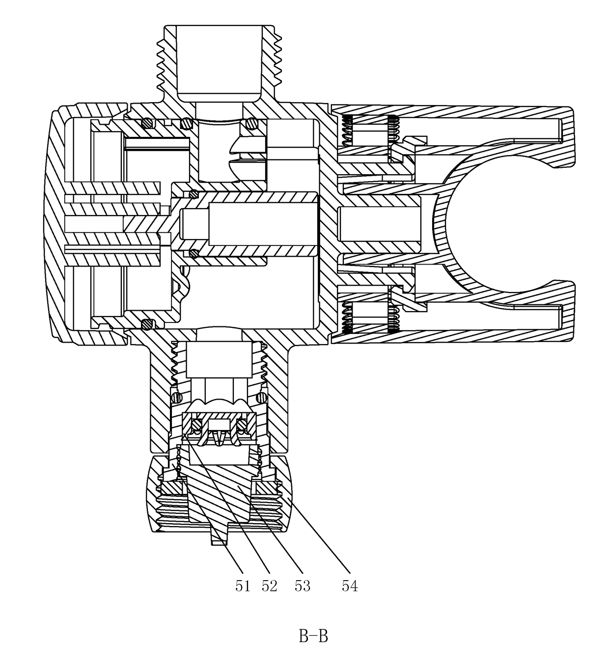
The invention provides a water separator with a shower seat that is securely connected to the valve through snap-fit joints. This avoids the potential problem of loose connection due to the valve becoming loose during use. The shower seat is designed to wear even after long-time use, ensuring continued reliability and performance. The valve can be easily operated with minimal adjusting force.

Problems solved by technology

When used over a long time, the connection between the shower seat and the valve body may get loose due to loosening of screw.
Since the rigid friction is likely to cause the reduction of frictional strength, thus reducing the rotational torque of the shower seat.
Due to this, problems such that the connection of the shower seat is unreliable, the shower seat or the shower get loose or even fallen and so on may occur.
Therefore, the operation is inconvenient.

Method used


Image

  • Water separator with shower seat
  • Water separator with shower seat
  • Water separator with shower seat

Examples


embodiment 1

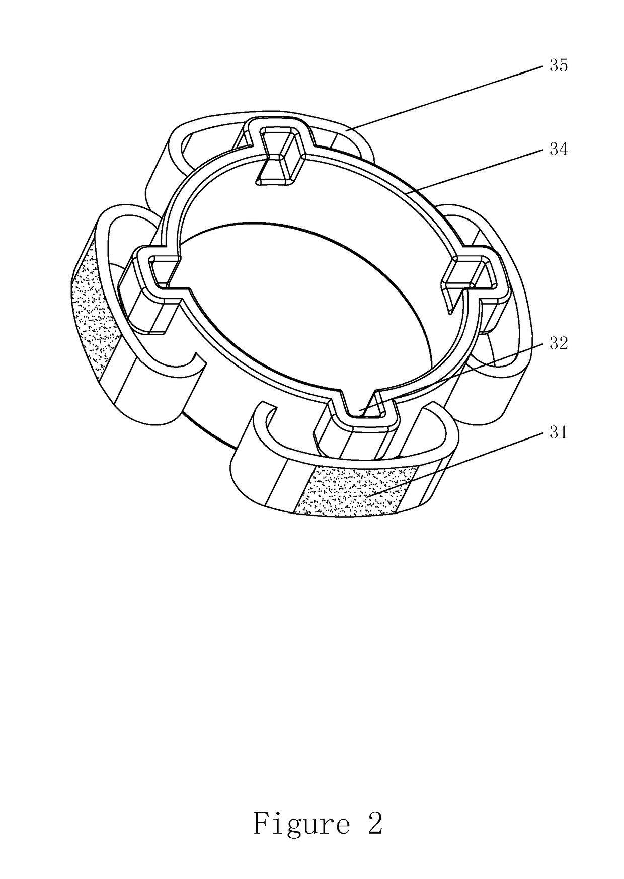
[0053]As shown in FIG. 4 to FIG. 6, the outer wall of the frictional unit 3 is provided with a first tooth-like protrusion 33. The tooth crest of the first tooth-like protrusion 33 forms the first frictional surface 31. The inner wall of the connecting chamber 21 of the shower seat 2 is provided with a first tooth-like recess 25. The tooth crest of the first tooth-like recess 25 forms the second frictional surface 23. The frictional unit 3 is provided with a hollow structure, which is used to enable the tooth crest of the first tooth-like protrusion 33 to deform radially when there is relative rotation between the shower seat 2 and the valve body 1, so as to facilitate the rotation of the first frictional surface 31 relative to the second frictional surface 23. When the shower seat 2 rotates with respect to the valve body 1, the tooth crest of the first tooth-like recess 25 rotates with respect to the tooth crest of the first tooth-like protrusion 33. When the shower seat 2 rotates ...

embodiment 2

[0056]As shown in FIG. 7 to FIG. 9, the outer wall of frictional unit 3 is provided with more than two second tooth-like protrusions 36. Second tooth-like protrusions 36 are circumferentially disposed on the peripheral surface of the frictional unit 3 at even intervals and the tooth crest of thereon forms the first frictional surface 31. A frictional unit receiving groove 26 is provided in the connecting chamber 21 of the shower seat 2 and the inner wall thereof is provided with a second tooth-like recess 27. The tooth crest of the second tooth-like recess 27 forms a second frictional surface 23. When the shower seat 2 rotates with respect to the valve body 1, the tooth crest of second tooth-like recess 27 rotates with respect to the tooth crest of the second tooth-like protrusion 36. When the shower seat 2 rotates in place on the valve body 1, the second tooth-like recess 27 on the inner wall of the frictional unit receiving groove 26 engages with the second tooth-like protrusion 3...


PUM


Abstract

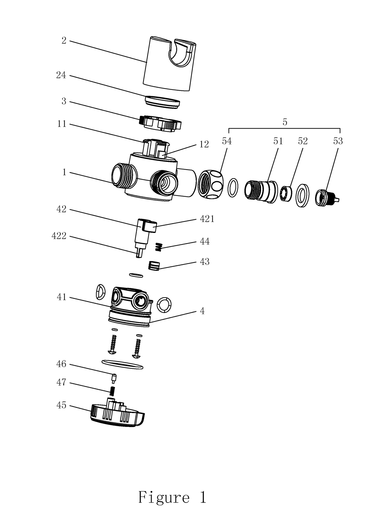
A water separator with a shower seat includes a valve body, a frictional unit, a shower seat, and a water outflow switching mechanism. The valve body is provided with a plurality of snap-fit joints disposed circumferentially. The frictional unit is mounted on the valve body and an outer wall thereof is provided with a first frictional surface. The shower seat is provided with a connecting chamber having an open end, and a snap-fit surface and a second frictional surface are circumferentially disposed in the connecting chamber, respectively. The water outflow switching mechanism is mounted in the valve body. Hook heads of the snap-fit joints are snapped to the snap-fit surface to prevent the shower seat from getting separated from the valve body. When the shower seat rotates with respect to the valve body, the first frictional surface and the second frictional surface rotate accordingly and interact with each other.

Description

CROSS REFERENCE TO RELATED APPLICATIONS[0001]This application is based upon and claims priority to Chinese Application No. 201720324843.6, filed on Mar. 29, 2017, the entire contents of which are incorporated herein by reference.TECHNICAL FIELD[0002]The present invention relates to the field of sanitation technology, more particularly, to a water separator with a shower seat.BACKGROUND OF THE INVENTION[0003]In currently available water separators with shower seat, the connection of the shower seat and the valve body is achieved by the following steps: providing a threaded hole on the valve body while providing a through hole in the clamping groove of the shower seat, passing a screw through the through hole of the shower seat, and locking it in the threaded hole of valve body such that the shower seat is fixed to the valve body. The rotational function of the shower seat is achieved by screwing or unscrewing the screw. When used over a long time, the connection between the shower se...

Claims


Application Information

Patent Timeline
IPC IPC(8): E03C1/02F16L37/084F16K11/085
CPCE03C1/023F16K11/0856F16L37/0847F16K11/074E03C1/06A01G25/16E03C1/025
Inventor LIN, XIAOFALIN, XIAOSHANLIU, QIQIAODENG, XIAOQINGXU, JUNGAO, JIANHUI
Owner FUJIAN XIHE SANITARY WARE TECH
Learn More