Ultrasonic flow meter

a flow meter and ultrasonic technology, applied in the direction of volume/mass flow measurement, measurement devices, instruments, etc., can solve the problems of difficult molds, difficult to mold, and positional limitations of ultrasonic flow meter installation, etc., to achieve compact structure, easy mounting, and less amount of use of expensive corrosion-resistant resin

Active Publication Date: 2018-10-04
RYUSOK CO LTD
View PDF7 Cites 3 Cited by
  • Summary
  • Abstract
  • Description
  • Claims
  • Application Information

AI Technical Summary

Benefits of technology

[0015]According to the ultrasonic flow meter of the invention, separately provided ultrasonic transceiver units are easily mounted on both sides ...

Problems solved by technology

The conduit portion is complicated in structure, and thus is difficult to mold by injection molding at one time.
In addition, since the lead wires 7a and 7b are led out in a direction of an extended line of the straight pipe portion 2, a problem of positional limitation for installation of the ultrasonic flow meter arises.
However, the corrosion-resistant resin is more expensive than general synthetic resins such as polyethylene and polypropylene.
Therefore, if the corrosion-resistant resin is used also for the cylindrical portions 5a and 5b ...

Method used


Image

  • Ultrasonic flow meter
  • Ultrasonic flow meter
  • Ultrasonic flow meter

Examples


example 1

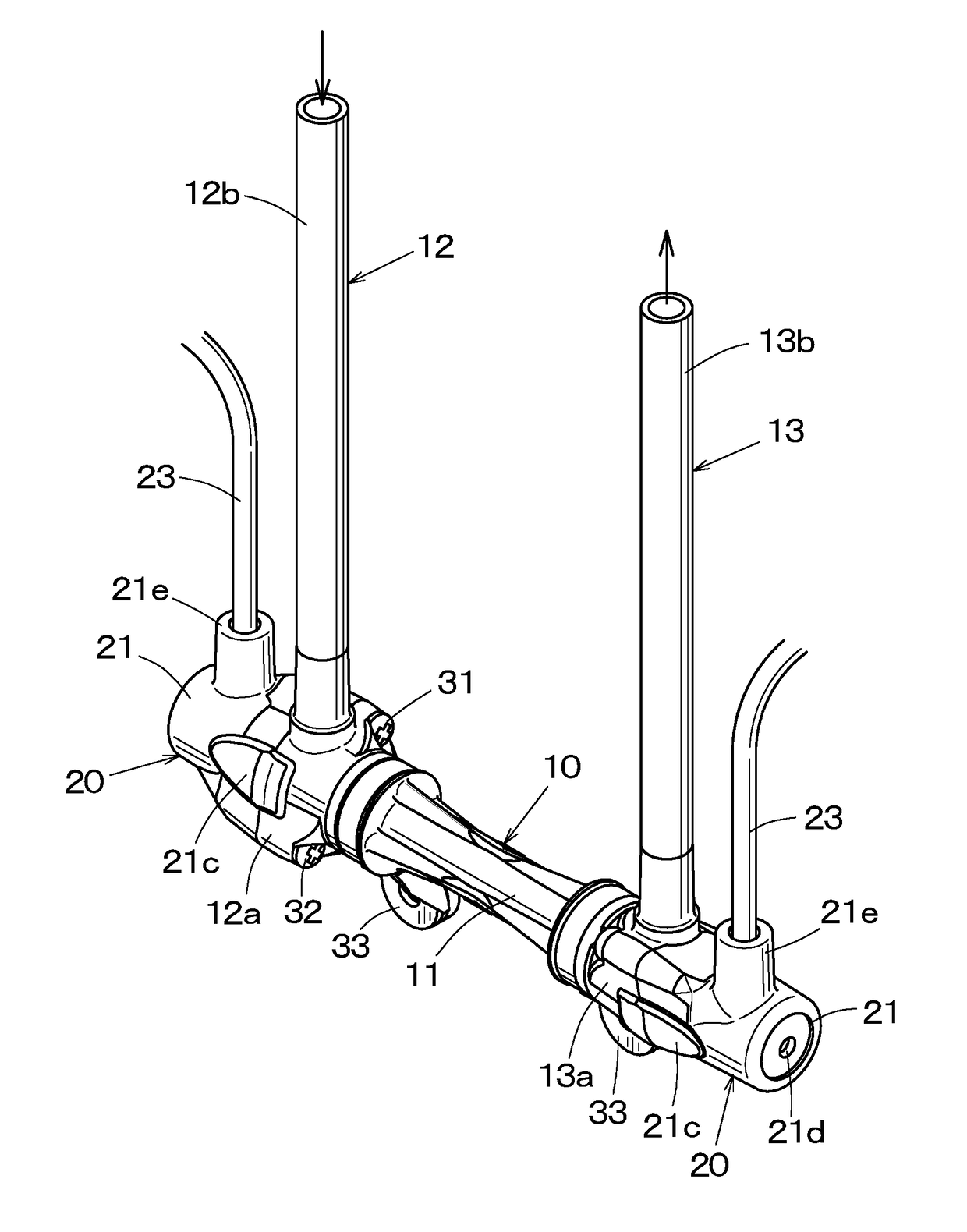
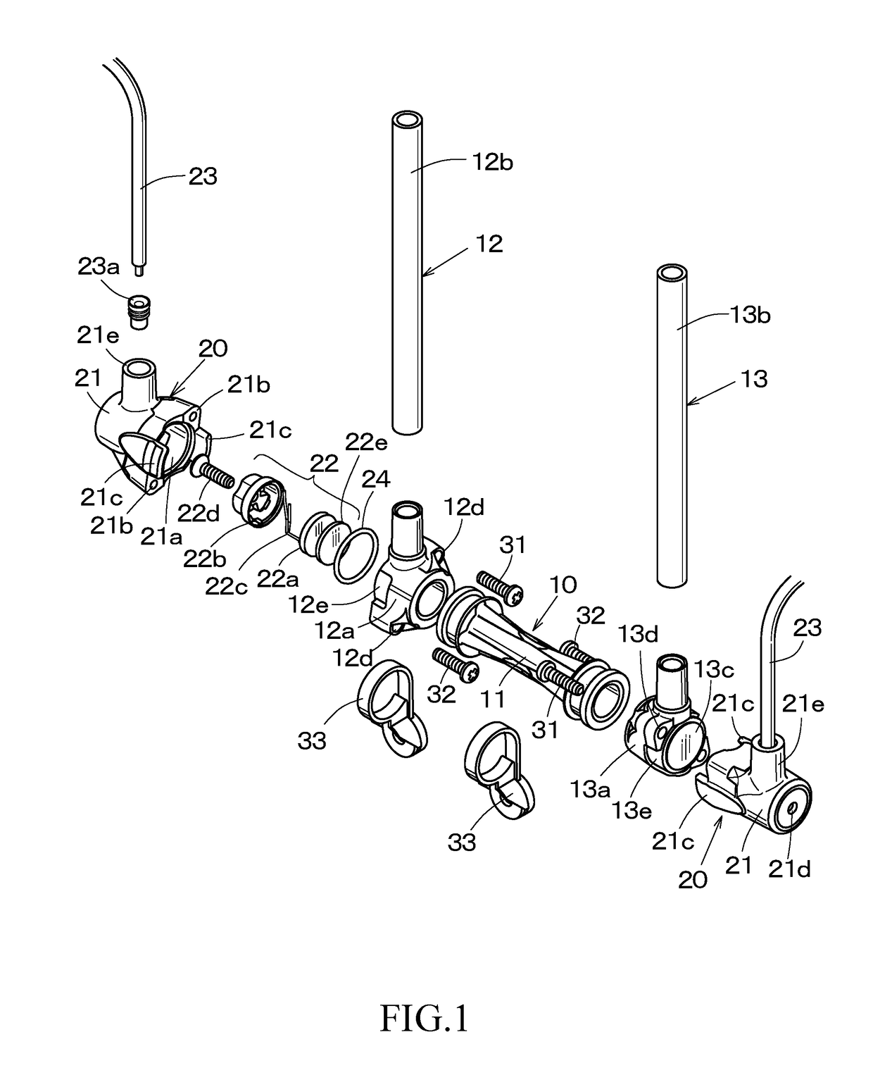
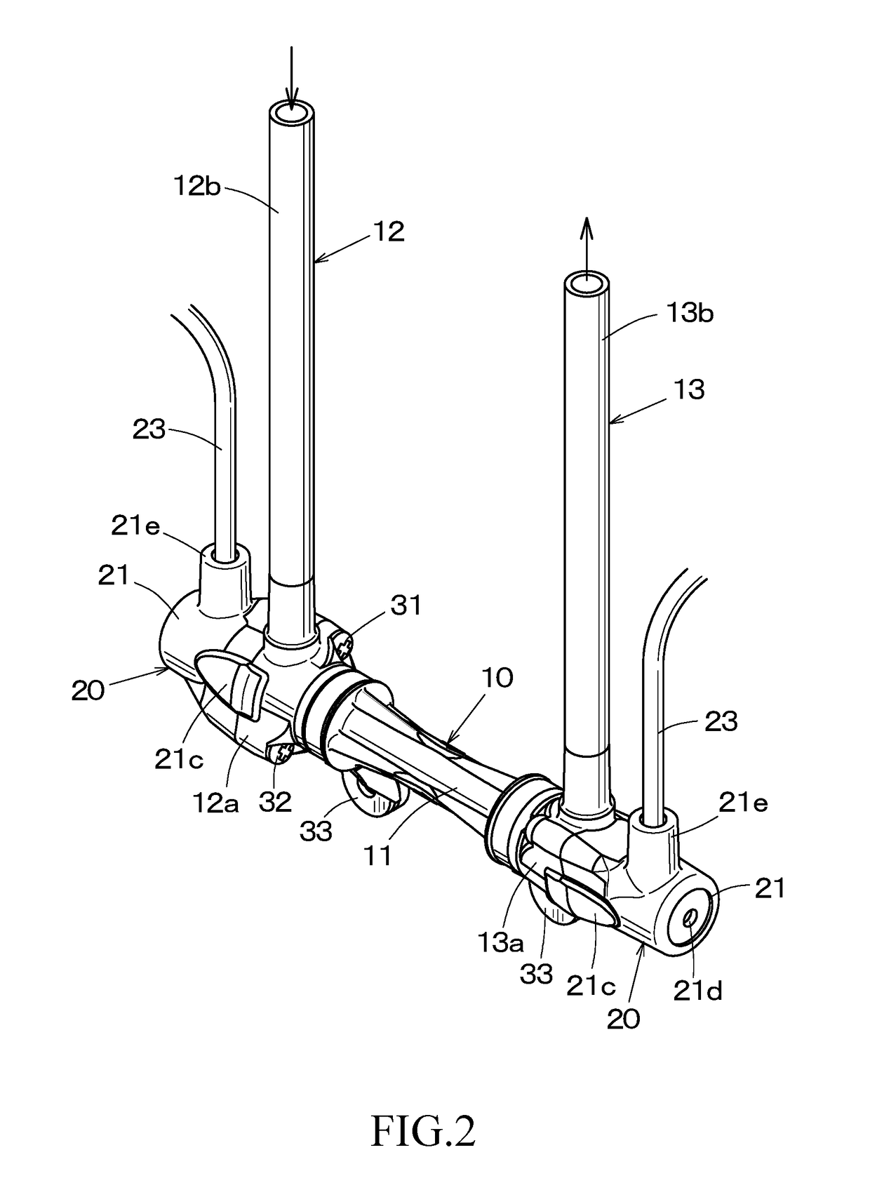
[0025]FIG. 1 is an exploded perspective view of an ultrasonic flow meter according to Example 1, FIG. 2 is a perspective view of an assembled state, FIG. 3 is a cross-sectional view, and FIG. 4 is a perspective view of a process of mounting an ultrasonic transceiver unit on a conduit portion.

[0026]The ultrasonic flow meter of Example 1 mainly includes a conduit portion 10 in which a fluid flows, and a pair of ultrasonic transceiver units 20 to be mounted on both sides of the conduit portion 10.

[0027]The conduit portion 10 includes a straight conduit 11, an inlet conduit 12 coupled to one end of the straight conduit 11 in an L-shape by thermal welding or the like to allow the fluid to flow therein from a direction perpendicular to the straight conduit 11, and an outlet conduit 13 coupled to the other end of the straight conduit 11 in an L-shape and allow the fluid to flow out from the straight conduit 11 to the direction perpendicular thereto. The inlet conduit 12 and the outlet cond...

example 2

[0059]FIG. 5 is an exploded perspective view of the ultrasonic flow meter according to Example 2, FIG. 6 is a cross-sectional view, FIG. 7 is an enlarged cross-sectional view of the ultrasonic transceiver unit, and FIG. 8 is a perspective view illustrating a process of mounting the ultrasonic transceiver unit on the conduit portion. An external perspective view is almost the same as that of Example 1. Note that the same reference numerals as those in Example 1 denote the same members.

[0060]While the piezoelectric elements 22a are directly disposed on the opened end sides of the covering members 21 of the ultrasonic transceiver units 20 in Example 1, front plates 26 formed of a synthetic resin are disposed on the opened end sides of the covering members 21 of two ultrasonic transceiver units 20′ in Example 2, so that the interiors of the covering members 21 are closed.

[0061]The front plate 26 is a synthetic resin plate formed of FRP or the like and capable of propagating ultrasonic w...


PUM


Abstract

An inlet conduit and an outlet conduit are disposed in a so-called crank shape with respect to a straight conduit. The straight conduit is provided with wall surfaces with which piezoelectric elements come into abutment from outside, and ultrasonic transceiver units are demountably mounted on the outside of the wall surfaces respectively. The two ultrasonic transceiver units have the same shape, and each include a covering member formed of a synthetic resin, the piezoelectric element provided in the covering member for transmitting and receiving an ultrasonic beam, and a cable connected to the piezoelectric element. The conduit portion and the ultrasonic transceiver unit are assembled separately. The ultrasonic transceiver units are disposed on both sides of the conduit portion and are coupled thereto with screws.

Description

BACKGROUND OF THE INVENTION1. Field of the Invention[0001]The present invention relates to an ultrasonic flow meter configured to measure a flow rate of a fluid in piping used in various industrial fields.2. Description of Related Art[0002]An ultrasonic flow meter includes piezoelectric elements for transmitting and receiving an ultrasonic beam fixed at, for example, both ends of a crank-shaped conduit portion. The piezoelectric elements measure times required for an ultrasonic beam to propagate from one end to the other end and from the other end to one end, respectively, of a conduit portion in which a fluid flows, and obtain a flow rate of the fluid flowing in the conduit portion from the difference between the respective propagating times.[0003]The crank-shaped conduit portion described above is typically formed of a synthetic resin, includes a straight pipe portion, an inlet conduit, and an outlet conduit, and requires mounting portions for the piezoelectric elements at both si...

Claims


Application Information

Patent Timeline
IPC IPC(8): G01F1/66
CPCG01F1/662G01F1/667G01F1/66
Inventor MURAKAMI, EIICHISAKIYAMA, KOHEI
Owner RYUSOK CO LTD
Why Eureka
Try Eureka