Planning system and method for maintaining a cycle time in an automobile factory

a technology of planning system and cycle time, which is applied in the direction of program control, total factory control, instruments, etc., can solve the problems of long conveyor belt, high cost of electronics to adjust the velocity in such heavy systems, and variation in the interval distance between lines

Active Publication Date: 2018-10-04
REXNORD FLATTOP EURO BV
View PDF9 Cites 6 Cited by
  • Summary
  • Abstract
  • Description
  • Claims
  • Application Information

AI Technical Summary

Benefits of technology

[0012]Virtual feedback markings can be shown from any position and may be more comprehensive for the driver placing the car than physical marks that are only on the conveyor belt. Preferably, the visual indicators are provided on a display screen. For example, the screen can be positioned at any position visible from the driver's seat. The screen may e.g. provide visual feedback whether the car is in the designated position. For example, a virtual marking can be displayed. By additionally showing a recorded image of the car that is being placed on the display screen, the driver can more cle...

Problems solved by technology

However, wear and tear of the conveyor belt may cause lengthening of the conveyor belt and thereby variations in the interval distance between the lines.
However, the electronics to adjust ...

Method used


Image

  • Planning system and method for maintaining a cycle time in an automobile factory
  • Planning system and method for maintaining a cycle time in an automobile factory
  • Planning system and method for maintaining a cycle time in an automobile factory

Examples


first embodiment

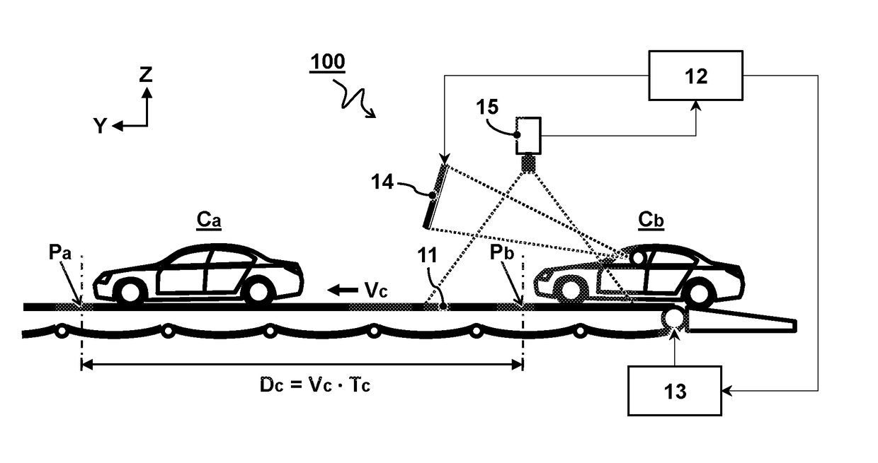
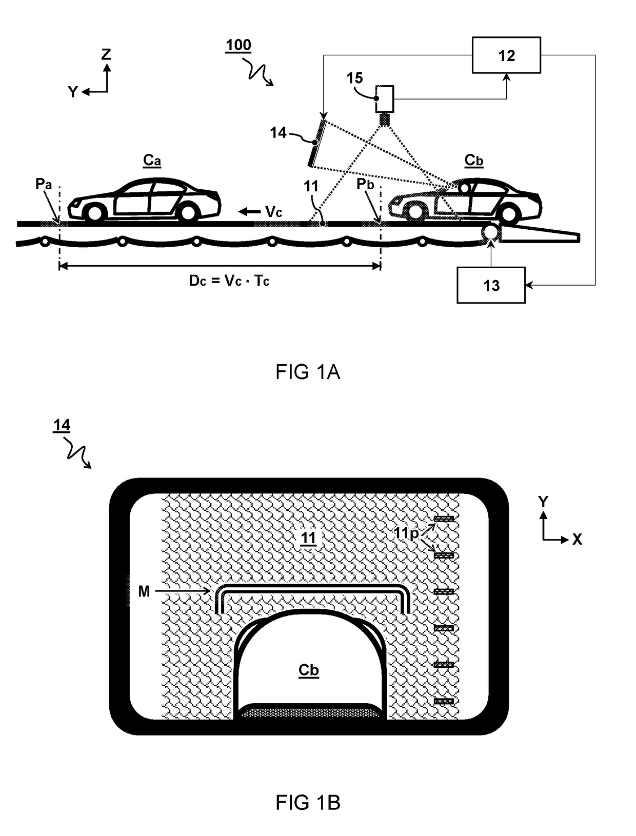
[0021]FIG. 1A shows a schematic side view of first embodiment of an automobile factory planning system 100. FIG. 1B shows a schematic view of a display screen 14 for use in the system of FIG. 1A.

[0022]The system 100 is configured to operate at a controlled cycle time Tc. In one embodiment, the cycle time Tc determines an interval wherein consecutive automobiles are to be manufactured. In another or further embodiment, the cycle time Tc is a time interval between subsequent vehicles passing a fixed point along the manufacturing line. For example, the factory comprises a plurality of work stations along the manufacturing path of the conveyor belt 11, wherein each work station is configured to perform a manufacturing step in accordance with the cycle time Tc. In one embodiment, the system comprises an input device (not shown) allowing adjustment of the cycle time Tc.

[0023]The system 100 comprises a conveyor belt 11. In the embodiment shown, the conveyor belt 11 is an endless belt. Typi...

second embodiment

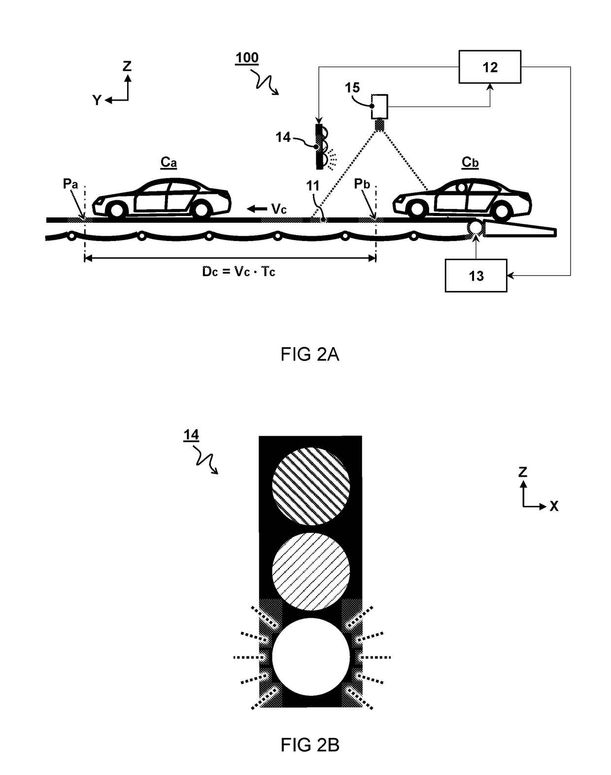
[0034]FIG. 2A shows a schematic side view of second embodiment of an automobile factory planning system 100. FIG. 2B shows a schematic view of a traffic light 14 for use in the system of FIG. 2A.

[0035]The second embodiment is similar as the first embodiment, described with reference to FIG. 1, but using a traffic light instead of a display screen. For example, the lighting is controlled as a function of a distance between an actual position of the next automobile Cb relative to its designated position Pb on the moving conveyor belt 11. For example, a green light means that the car can still move forward, while a red light means the car must stop. It is noted that the present system differs from other applications of a traffic light in that the designated position is not fixed but moves with the conveyor belt as a function of the displacement velocity Vc and cycle time Tc.

[0036]Since the image of the car Cb is not displayed in this embodiment, a camera 15 is not necessary but can nev...

third embodiment

[0037]FIG. 3A shows a schematic side view of third embodiment of an automobile factory planning system. FIG. 3B shows a schematic top view of a projected virtual marking M in the system of FIG. 3A.

[0038]In the embodiment shown, the feedback device comprises a light projector configured to project the visual indicator M onto the conveyor belt 11 moving in sync with the displacement velocity Vc of the conveyor belt 11. More particularly, for example, the feedback device comprises a laser system configured to project the visual indicator M as a laser pattern onto the conveyor belt 11 moving in sync with the displacement velocity Vc of the conveyor belt 11.

[0039]For the purpose of clarity and a concise description, features are described herein as part of the same or separate embodiments, however, it will be appreciated that the scope of the invention may include embodiments having combinations of all or some of the features described. For example, while embodiments were shown for provi...


PUM


Abstract

An automobile factory planning system and method for controlling a cycle time. The system comprises a conveyor belt configured to transport a plurality of automobiles at a controlled displacement velocity along a manufacturing path through the automobile factory. A feedback device is configured to provide a visual indicator of a designated position at which a next automobile is to be placed on the conveyor belt relative to the position of a previous automobile. The designated position is calculated as a function of the cycle time and the displacement velocity of the conveyor belt.

Description

CROSS-REFERENCE TO RELATED APPLICATIONS[0001]This application represents the national stage entry of PCT International Application No. PCT / NL2016 / 050675 filed Oct. 3, 2016 and claims priority to Dutch Patent Application No. NL 2015542 filed Oct. 1, 2015. The contents of these applications are hereby incorporated by reference as if set forth in their entirety herein.STATEMENT REGARDING FEDERALLY SPONSORED RESEARCH OR DEVELOPMENT[0002]Not applicable.TECHNICAL FIELD AND BACKGROUND[0003]The present disclosure relates to an automobile factory planning system, a feedback device for maintaining a cycle time, use of a modular conveyor mat in the planning system, a method for controlling a cycle time, and a computer readable medium to execute the method.[0004]In industrial manufacturing, the ‘takt time’ (from the German Taktzeit) refers to the average unit production time needed to meet customer demand. The ‘cycle time’ refers to the time that elapses between two consecutive unit completions...

Claims


Application Information

Patent Timeline
IPC IPC(8): G05B19/418B62D65/18B65G35/02
CPCG05B19/41865B62D65/18B65G35/02B65G2201/0294Y02P90/02
Inventor MENKE, CORNELIS HENDRIK MIJNDERT
Owner REXNORD FLATTOP EURO BV
Why Eureka
Try Eureka