Supercharge Your Innovation With Domain-Expert AI Agents!

Data bus logger

a data bus and logger technology, applied in the field of data bus communication, can solve problems such as difficulty in determining when a fault occurs in a system having a shared data bus, faults may be caused or triggered, and logging technologies may miss bus glitches

Active Publication Date: 2018-10-04
GOVERNMENT OF THE UNITED STATES AS REPRESENTED BY THE SEC OF THE AIR FORCE
View PDF3 Cites 6 Cited by
  • Summary
  • Abstract
  • Description
  • Claims
  • Application Information

AI Technical Summary

Benefits of technology

The patent text describes a solution for capturing and storing data on a data bus. The invention includes a device that captures both non-inverted and inverted data streams, converts them into packet format, and stores them in a non-volatile memory. This avoids the issue of race conditions and other issues that may occur when data is captured on a data bus. The technical effect of this solution is improved data accuracy and reliability for logging communication on a data bus.

Problems solved by technology

It is often difficult to determine when a fault occurs in a system having a shared data bus, particularly while running tests and during normal operations.
Faults may be caused or triggered by messages that transfer data or send control messages to devices over such data buses.
These logging technologies may miss bus glitches and packet collisions occurring on the monitored shared data bus because they decode messages before saving them, losing the raw (pre-decoded) signal information.
For this and other reasons, when glitches are missed or collisions occur, these logging technologies can miss these anomalies.
Shared data bus logging systems may have other hurdles associated with logging data being continuously streamed.
Because of limitations in their storage capacity, some commercial data loggers limit the amount of data being collected to only valid data packets and do not capture all data being streamed.

Method used


Image

  • Data bus logger
  • Data bus logger
  • Data bus logger

Examples


Embodiment Construction

[0021]The various methods, systems, apparatuses, and devices described herein generally provide for improved logging of data bus communications between remote terminals of a data bus.

[0022]While this invention is susceptible of embodiments in many different forms, there is shown in the drawings and will herein be described in detail specific embodiments, with the understanding that the present disclosure is to be considered as an example of the principles of the invention and not intended to limit the invention to the specific embodiments shown and described.

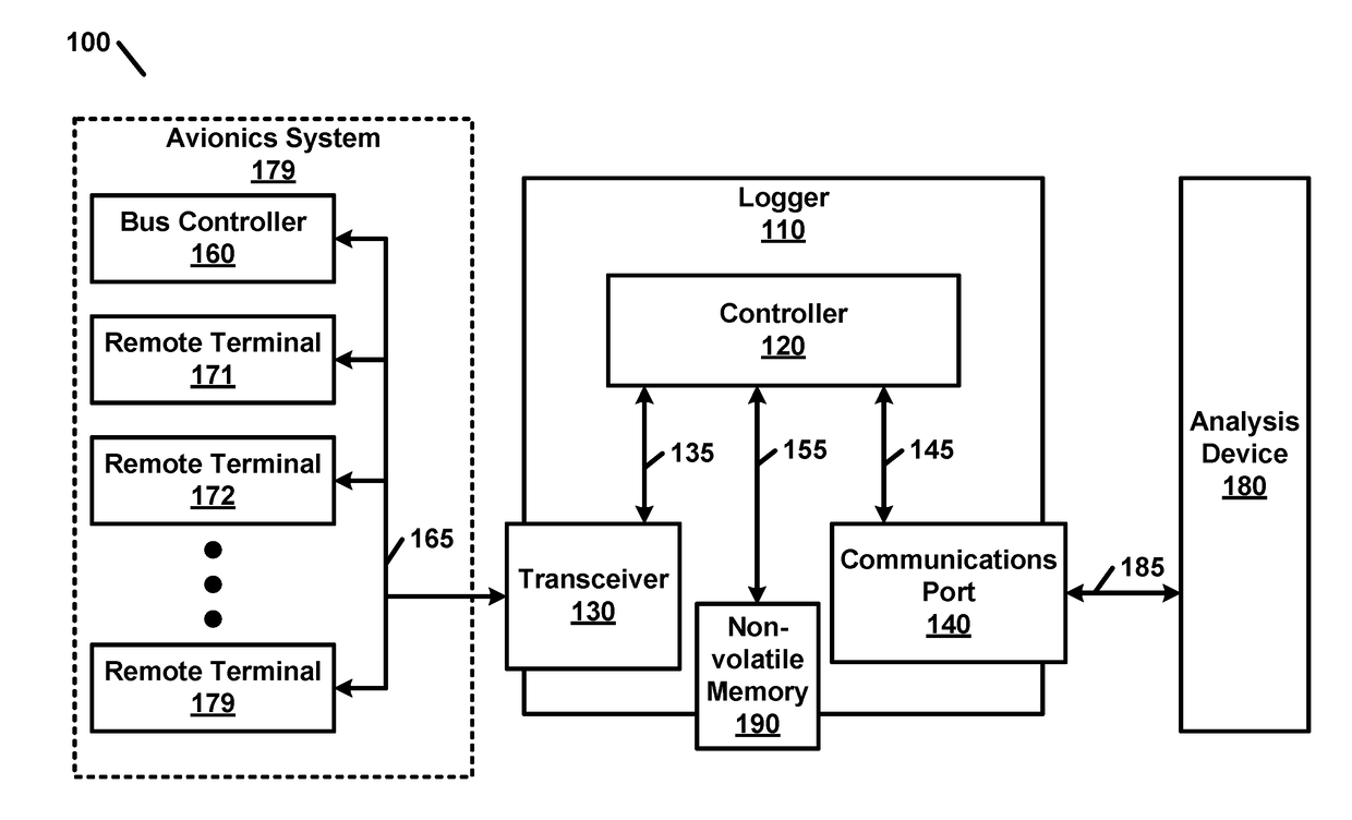
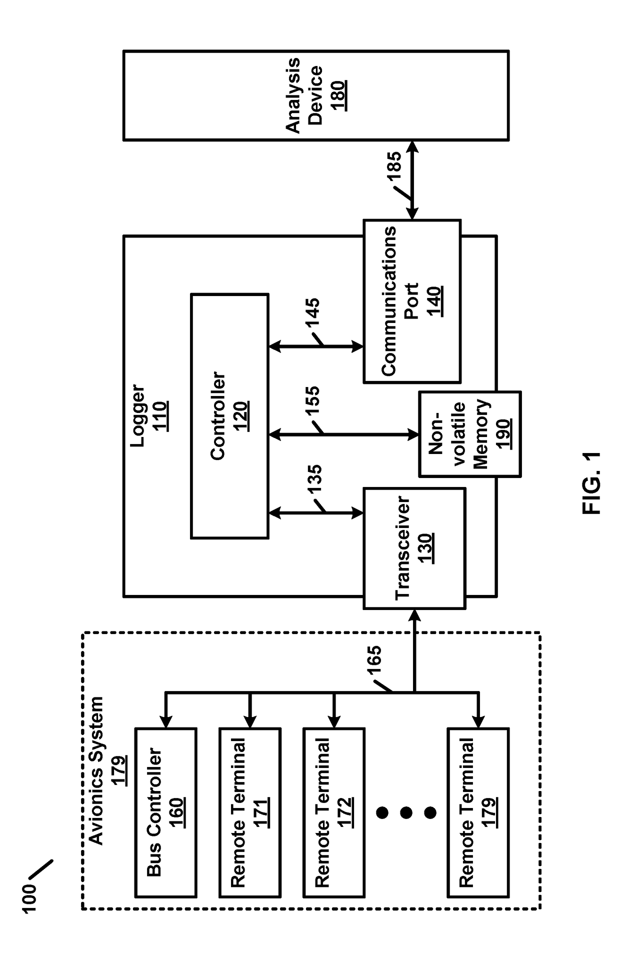
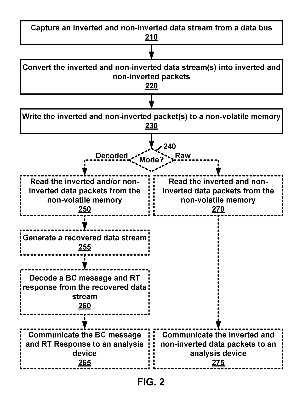
[0023]Embodiments of the present invention include a data logger that may be configured to continuously digitize data streams from a plurality of differential transmission lines connected to one or more data busses, packetize the digitized data stream, and write the packetized data to non-volatile memory. Additionally, embodiments may play back the logged data in a raw mode and / or decoded mode. The logged data may be employed in...


PUM


Abstract

A system having a data bus, bus controller(s), remote terminal(s) and a logger. The data bus has an inverted differential line and a non-inverted differential line. The bus controller(s) are electrically coupled to the data bus. The remote terminal(s) are electrically coupled to the data bus. The logger has a bus transceiver and a controller. The bus transceiver is electrically coupled to the data bus. The controller is electrically coupled to the transceiver. The controller is configured to: capture a non-inverted data stream from the bus transceiver, capture an inverted data stream from the bus transceiver, convert the non-inverted data stream into non-inverted packets having a packet size, convert the inverted data stream into inverted packets having the packet size; and write the non-inverted data packets and inverted data packets to a non-volatile memory.

Description

CROSS REFERENCE TO RELATED APPLICATIONS[0001]This application claims the benefit of and priority to U.S. Provisional Application Ser. No. 62 / 478,849, entitled “Data Bus Logger,” filed on Mar. 30, 2017, the entirety of which is incorporated by reference herein.STATEMENT OF GOVERNMENT INTEREST[0002]The invention described herein may be manufactured and used by or for the Government of the United States for all governmental purposes without the payment of any royalty.FIELD OF THE INVENTION[0003]The present disclosure relates generally to data bus communications and, more particularly, to logging communications on a data bus.BACKGROUND OF THE INVENTION[0004]It is often difficult to determine when a fault occurs in a system having a shared data bus, particularly while running tests and during normal operations. Faults may be caused or triggered by messages that transfer data or send control messages to devices over such data buses. Shared data buses may be employed in systems such as Sup...

Claims


Application Information

Patent Timeline
IPC IPC(8): G06F13/40G06F13/12G06F13/16
CPCG06F13/4018G06F13/4022G06F13/124G06F13/1694
Inventor PRENTICE, DAVID C.
Owner GOVERNMENT OF THE UNITED STATES AS REPRESENTED BY THE SEC OF THE AIR FORCE
Features
  • R&D
  • Intellectual Property
  • Life Sciences
  • Materials
  • Tech Scout
  • Unparalleled Data Quality
  • Higher Quality Content
  • 60% Fewer Hallucinations
Learn More