Power factor correction device, and current sensing method and apparatus thereof

a power factor and current sensing technology, applied in the field of power factor correction technology, can solve the problems of large distortion of output signal, increase in sensing accuracy of sense current, and accumulation of effect in circuit, and achieve the effect of universal application and easy implementation

Active Publication Date: 2018-10-04
MURATA MFG CO LTD
View PDF0 Cites 6 Cited by
  • Summary
  • Abstract
  • Description
  • Claims
  • Application Information

AI Technical Summary

Benefits of technology

[0032]Further, a position of the converter in PFC devices in preferred embodiments of the present invention may be one of various positions. Specifically, the converter may be disposed at one of the following positions: between the first terminal of the inductor and the first output terminal of the rectifier bridge, between the second terminal of the inductor and the first terminal of the at least one main switch, between the second output terminal of the rectifier bridge and the second terminal of the at least one main switch, or in the first, second, third or fourth bridge arm, which makes solutions of the preferred embodiments of the present invention easy to implement and universally applicable.

Problems solved by technology

When a negative power supply port of an operational amplifier of the differential operational amplifier circuit is grounded, an amplitude of an output signal of the differential operational amplifier circuit may be close to 0V, which causes large distortion of the output signal.
Even worse, this error effect accumulates in the circuit, which makes the sensing of the sense current Isense more and more inaccurate.
Thus, in the PFC device, as the actual value of the offset voltage does not match its nominal value, current sensing accuracy of the PFC device may be seriously affected.

Method used


Image

  • Power factor correction device, and current sensing method and apparatus thereof
  • Power factor correction device, and current sensing method and apparatus thereof
  • Power factor correction device, and current sensing method and apparatus thereof

Examples


Embodiment Construction

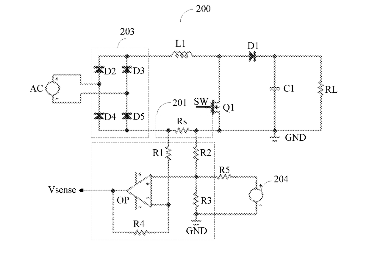
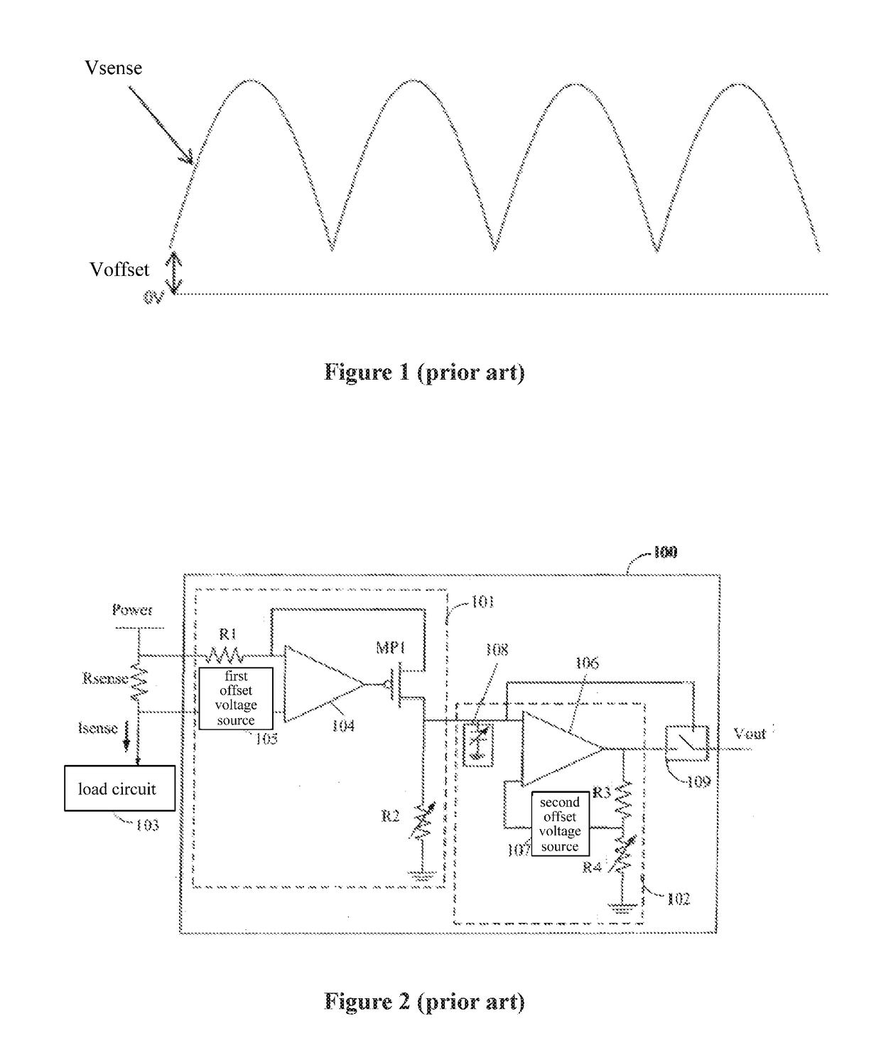
[0046]As described in the background, in the existing techniques, during the calculation of the current to be sensed in the PFC device using the offset voltage, the nominal voltage value of the constant voltage source to generate the offset voltage is used to calculate the current to be sensed. When objective factors, such as aging or thermal effects, act on the constant voltage source, the actual value of the offset voltage does not match the nominal value, which seriously affects the current sensing accuracy of the PFC device.

[0047]The inventor of preferred embodiments of the present invention analyzed the current sensing methods for PFC devices in the existing techniques.

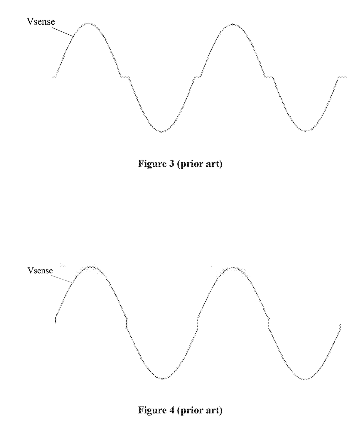
[0048]First, the inventor discovered that, as shown in FIGS. 3 and 4, when the offset voltage Voffset is too high, that is, the actual value of the offset voltage Voffset is higher than its nominal value, the current Isense to be sensed which is obtained in the PFC device has a distortion, and similarly, when the...


PUM


Abstract

A PFC device includes at least one main switch, a converter that converts a current to be sensed in the PFC device into a voltage to be sensed, the PFC device generating a switch control signal to control the at least one main switch based on the current to be sensed, and a voltage sensor that receives the voltage to be sensed and an offset voltage, and senses the voltage to be sensed using the offset voltage to output a sense voltage. A method includes sampling the sense voltage, determining a sense value of the offset voltage based on a sampling result, and calculating the current to be sensed based on a difference between the sense voltage and the sense value.

Description

CROSS REFERENCE TO RELATED APPLICATIONS[0001]This application claims the benefit of priority to Chinese Patent Application No. 201710201579.1 filed on Mar. 29, 2017. The entire contents of this application are hereby incorporated herein by reference.BACKGROUND OF THE INVENTION1. Field of the Invention[0002]The present invention relates to power factor correction (PFC) technology, and more particularly, to a PFC device, and a current sensing method and apparatus thereof.2. Description of the Related Art[0003]Power factor (PF) is a parameter used for measuring power consumption efficiency of electrical equipment. To improve the power consumption efficiency, PFC is usually performed to an alternating current (AC) input signal before the AC input signal is supplied to the electrical equipment. A PFC device usually increases PF by reducing a phase difference between a voltage and a current. Generally, the PFC device may include at least one main switch (also referred to as a power switch...

Claims


Application Information

Patent Timeline
Patent Type & Authority Applications(United States)
IPC IPC(8): H02M1/42G01R19/10
CPCH02M1/4208G01R19/10H02M2001/0009G01R17/16G01R19/2509G01R19/2513H02M1/0009H02M1/4225G01R19/0092Y02B70/10Y02P80/10H02M1/0012
Inventor CHAN, CHUK HUNG
Owner MURATA MFG CO LTD
Why Eureka
Try Eureka