Eureka AIR delivers breakthrough ideas for toughest innovation challenges, trusted by R&D personnel around the world.

Method of Fluid Flow Measurement Using Nozzle Bank

Active Publication Date: 2018-10-11
CANADA PIPELINE ACCESSORIES
View PDF5 Cites 0 Cited by
  • Summary
  • Abstract
  • Description
  • Claims
  • Application Information

AI Technical Summary

Benefits of technology

The present invention relates to a system and method for accurately measuring the flow rate of a fluid in a pipeline without the need for thermodynamic or fluid dynamic calculations. This is achieved by measuring the flow rate of at least one stream partitioned by a stepped nozzle. The invention has the advantage of being able to measure the flow rate of the fluid without interfering with its flow. The text also mentions that the invention can be used in various combinations and integrations with other embodiments described herein.

Problems solved by technology

However, there are inherent uncertainties associated with calculating flow rates in this manner.
This boundary layer effect adversely affects measurement accuracy.

Method used


Image

  • Method of Fluid Flow Measurement Using Nozzle Bank
  • Method of Fluid Flow Measurement Using Nozzle Bank
  • Method of Fluid Flow Measurement Using Nozzle Bank

Examples


Embodiment Construction

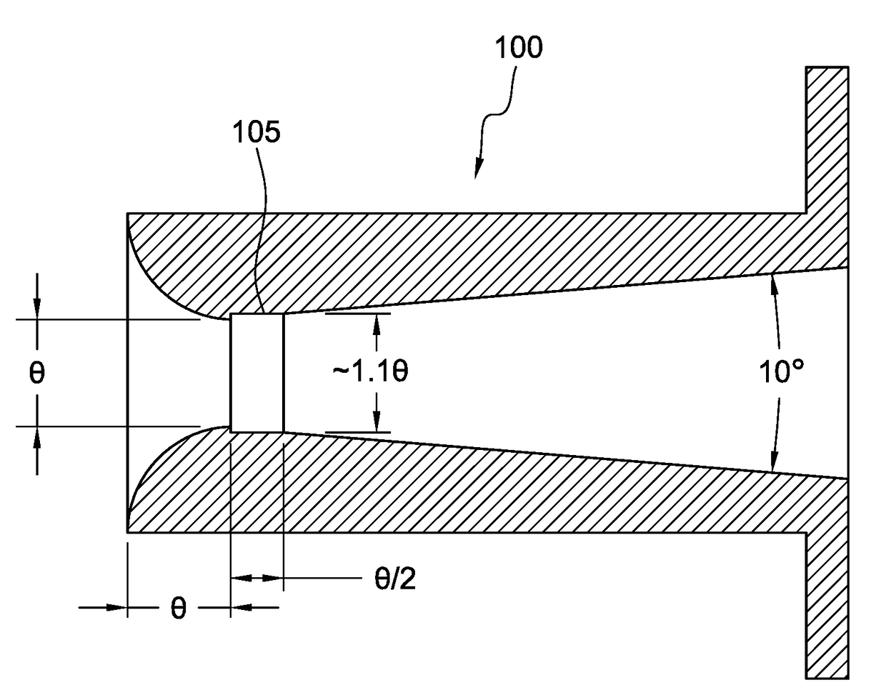
[0019]The present invention relates to a nozzle having a single step and the use of a nozzle bank comprising a plurality of the stepped nozzles for measuring fluid flow in a pipeline.

[0020]According to the present invention, a nozzle has a single step within the nozzle throat that causes an oblique shock wave in the throat of the nozzle. This oblique shock wave effectively closes off the unaccounted for boundary layer flow in the nozzle, thereby causing the mass flow rate to be extremely accurate, accounted for, and stable.

[0021]According to the present invention, a nozzle 100 has a single step 105 at about 1 throat diameter θ from an inlet plane of the nozzle, as shown in FIG. 1.

[0022]In specific embodiments, the single step comprises an increase in diameter corresponding to about 10% of the throat diameter. Thus, at about 1 throat diameter from the inlet plane of the nozzle, there is a cut machined into the wall of the nozzle so that the throat diameter increases about 10%. In spe...


PUM


Abstract

A method for measuring fluid flow within a fluid flow pipe includes partitioning a fluid flow within a pipeline with a nozzle bank, wherein a predetermined number of stepped nozzles is open; measuring the fluid flow in at least one partitioned fluid stream with at least one mass flow device; and calculating a total fluid flow within the pipeline. The nozzle bank includes a plurality of nozzles, each nozzle having a single step at about 1 throat diameter from an inlet plane of the nozzle, wherein the single step is an increase corresponding to about 10% of the throat diameter and has a length of about throat diameter / 2.

Description

[0001]This application claims priority to U.S. Ser. No. 62 / 481,871 filed in the U.S. Patent and Trademark Office on Apr. 5, 2017, the entirety of which is incorporated herein by reference.FIELD OF INVENTION[0002]The present invention relates to a nozzle having a single step and use of a nozzle bank comprising a plurality of the stepped nozzles for measuring fluid flow in a pipeline, for example, chemical, natural gas, or other gas phase fluid pipelines.[0003]Flow measurement accuracy is dependent on using pressure, temperature, and fluid composition to determine flow rate. The nozzle bank of the present invention lessens or eliminates the need to calculate pressure and temperature in a pipeline by using stepped nozzles to partition the fluid flow into at least one separate, smaller portion that can be measured directly with a mass flow device, like a gravimetric meter prover or a mass flow meter.BACKGROUND OF INVENTION[0004]Existing sonic nozzles are utilized in industry as flow met...

Claims


Application Information

Patent Timeline
IPC IPC(8): G01F1/84
CPCG01F1/8477G01F1/8413G01F1/42G01F1/84
Inventor SAWCHUK, BLAINESAWCHUK, DALESAWCHUK, DANIEL
Owner CANADA PIPELINE ACCESSORIES
Why Eureka
Eureka Blog
Learn More