
Method and Apparatus for Separating Seismic Diffracted Wave

a technology of diffracted waves and methods, applied in the field of seismic exploration, can solve the problems of inability to effectively identify the geological bodies inability to finely image geological bodies, and low imaging resolution of the carbonate stratum structure, so as to improve the amplitude integrity and waveform consistency of separated waves

Inactive Publication Date: 2018-10-11
INST OF GEOLOGY & GEOPHYSICS CHINESE ACAD OF SCI
View PDF3 Cites 9 Cited by
  • Summary
  • Abstract
  • Description
  • Claims
  • Application Information

AI Technical Summary

Benefits of technology

The present invention provides a method and apparatus for separating seismic diffracted waves to improve their amplitude integrity and waveform consistency. This is achieved by performing wave field back-propagation processing on seismic shot gather data carrying underground geological information in a preset geological region to obtain the azimuth, emergence angle, and amplitude information of propagation rays corresponding to the underground imaging points. Based on this information, a three-dimensional angle domain imaging matrix is generated and a low-rank matrix component is separated from it, which is determined as the seismic diffracted wave. This separation improves the amplitude integrity, consistency, and resolution of imaging of geological structures.

Problems solved by technology

However, carbonate stratum structures in some regions are quite special so that the formation and distribution of the carbonate reservoirs are relatively complex, causing it unable to finely image geological bodies, such as karst caves and cracks.
In the prior art, the seismic exploration in the petroleum industry mainly relies on the reflected wave, but the resolution of exploration through the reflected wave is limited, making it unable to effectively identify the geological bodies of the carbonate stratum structures.
However, in the collected three-dimensional shot gather data, the diffracted wave has highly similar kinematic characteristics to the reflected wave, and is hard to be effectively processed merely through a wave-field separating method in the conventional kinematics, resulting in low imaging resolutions of the carbonate stratum structures.
An effective solution has not yet been put forward to the above problem that amplitude integrity and waveform consistency of the diffracted wave separated by the above manner of separating the seismic diffracted wave are relatively poor.

Method used


Image

  • Method and Apparatus for Separating Seismic Diffracted Wave
  • Method and Apparatus for Separating Seismic Diffracted Wave
  • Method and Apparatus for Separating Seismic Diffracted Wave

Examples


example 1

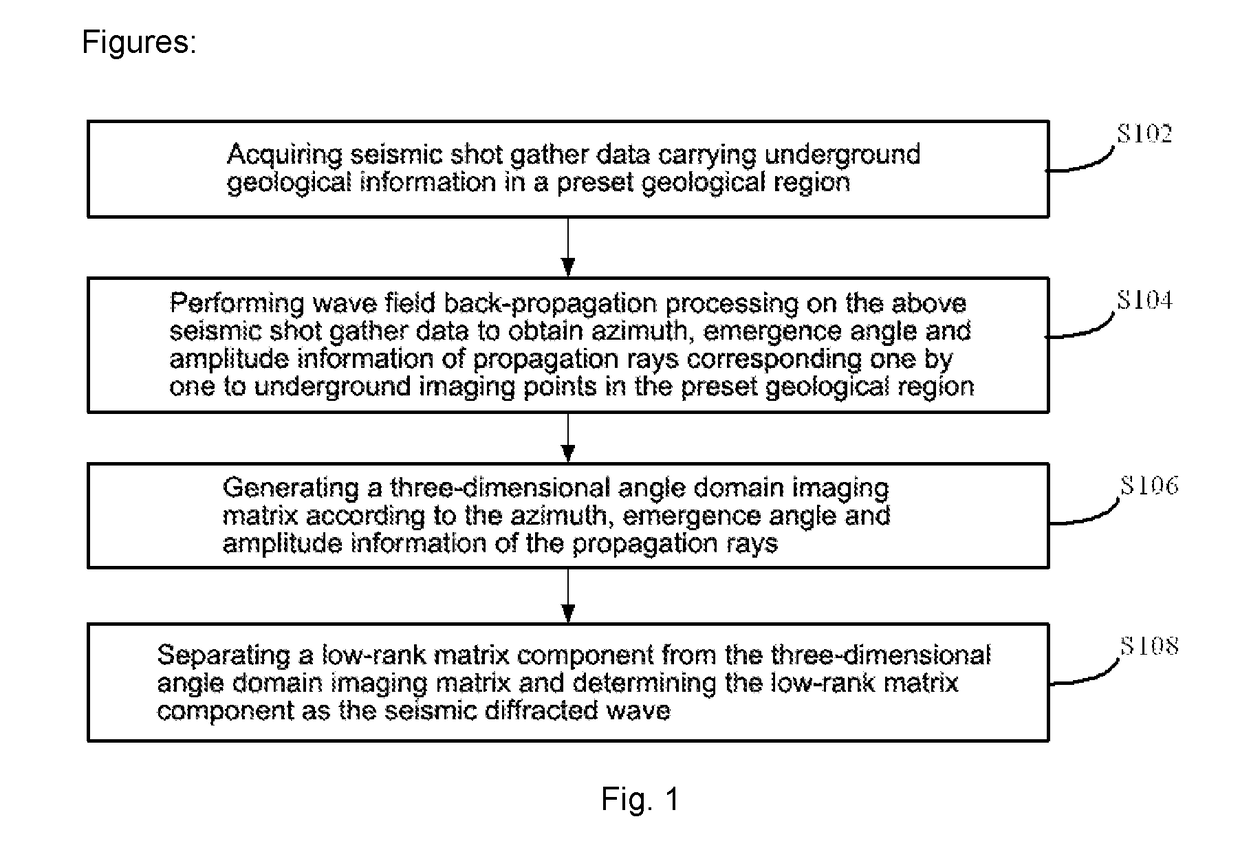
[0028]Referring to a flow chart of a method for separating a seismic diffracted wave shown in FIG. 1, the method comprises the following steps:

[0029]Step S102, acquiring seismic shot gather data carrying underground geological information in a preset geological region, wherein the underground geological information comprises geological structure information and geological lithology change information; specifically, the underground geological information may be information such as stratum structure, fault, karst cave and lithology sudden-change point;

[0030]Step S104, performing wave field back-propagation processing on the above seismic shot gather data to obtain azimuth, emergence angle and amplitude information of propagation rays corresponding one by one to underground imaging points in the preset geological region;

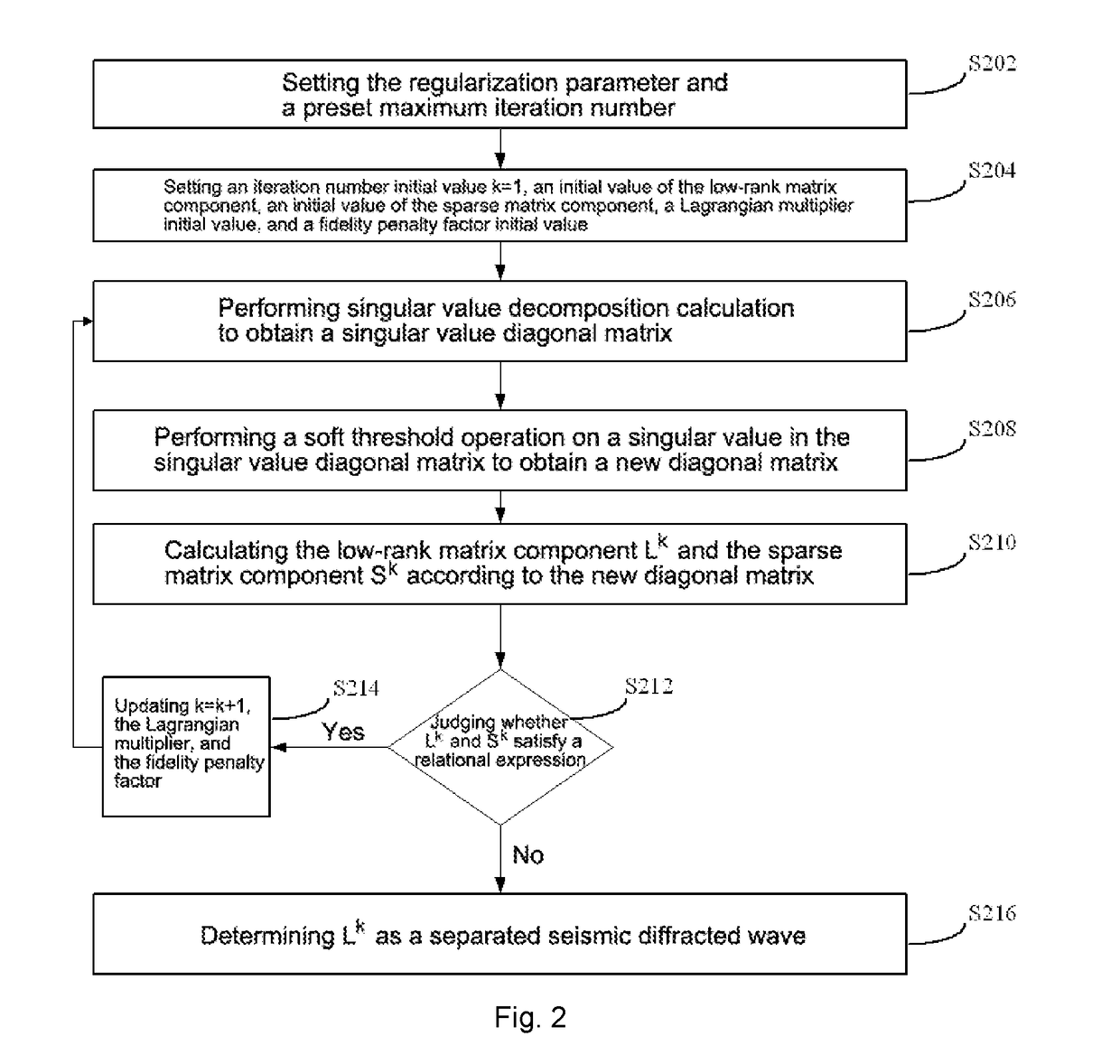
[0031]Step S106, generating a three-dimensional angle domain imaging matrix according to the azimuth, emergence angle and amplitude information of the propagation rays,...

example 2

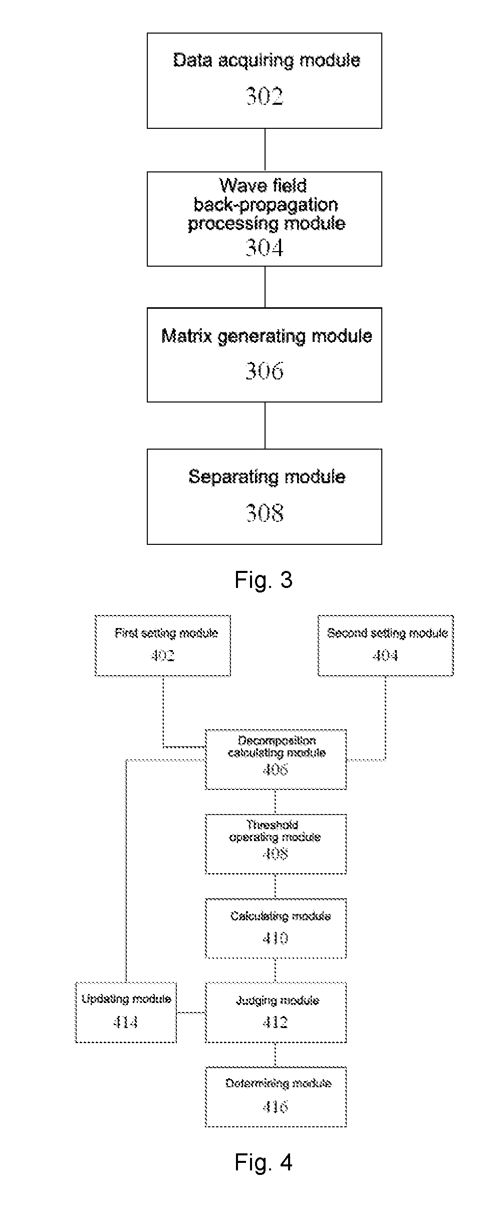
[0055]Corresponding to the above method example, referring to a structural schematic diagram of an apparatus for separating a seismic diffracted wave shown in FIG. 3, the apparatus comprises the following parts:

[0056]a data acquiring module 302, configured to acquire seismic shot gather data carrying underground geological information in a preset geological region, wherein the underground geological information comprises geological structure information and geological lithology change information;

[0057]a wave field back-propagation processing module 304, configured to perform wave field back-propagation processing on the seismic shot gather data to obtain azimuth, emergence angle and amplitude information of propagation rays corresponding one by one to underground imaging points in the preset geological region;

[0058]a matrix generating module 306, configured to generate a three-dimensional angle domain imaging matrix according to the azimuth, emergence angle and amplitude informatio...


PUM


Abstract

Method and apparatus for separating seismic diffracted waves, in seismic exploration field. The method comprises acquiring seismic shot gather data carrying underground geological information in preset geological region; inputting preprocessed single-shot data obtained by preprocessing seismic shot gather data and a preset migration velocity model to three-dimensional single-shot angle domain imaging formula and performing wave field back-propagation processing on the seismic shot gather data to obtain information of azimuth, emergence angle and amplitude of propagation rays, according to which three-dimensional angle domain imaging matrix is generated, the obtained information corresponding one by one to underground imaging points in the preset geological region; separating low-rank matrix component from the three-dimensional angle domain imaging matrix and determining the low-rank matrix component as the seismic diffracted wave through a preset three-dimensional diffracted wave separating model, improving amplitude integrity and waveform consistency of separated diffracted waves and imaging resolution of geological structures.

Description

CROSS REFERENCE TO RELATED APPLICATIONS[0001]The present application claims the priority of the Chinese Patent Application No. 201710019616.7, entitled “Method and Apparatus for Separating Seismic Diffracted Wave”, filed with the Chinese Patent Office on Jan. 10, 2017, the entity of which is incorporated herein by reference.TECHNICAL FIELD[0002]The present invention relates to the technical field of seismic exploration, and particularly to a method and an apparatus for separating a seismic diffracted wave.BACKGROUND ART[0003]Carbonate oil-gas reservoir has become a main field for increasing reserves and production of oil-gas resources. However, carbonate stratum structures in some regions are quite special so that the formation and distribution of the carbonate reservoirs are relatively complex, causing it unable to finely image geological bodies, such as karst caves and cracks.[0004]In the prior art, the seismic exploration in the petroleum industry mainly relies on the reflected w...

Claims


Application Information

Patent Timeline
IPC IPC(8): G01V1/30
CPCG01V1/302G01V1/28G01V1/325G01V1/36G01V2210/512G01V2210/56G01V2210/632G01V2210/67
Inventor YU, CAIXIAWANG, YANFEI
Owner INST OF GEOLOGY & GEOPHYSICS CHINESE ACAD OF SCI
Learn More