Complementary Plasmonic Device and Method

a plasmonic device and plasmonic technology, applied in the field of surface plasmonic devices, can solve the problem of not yet using basic components of plasmonics

Active Publication Date: 2018-10-11
THE UNITED STATES OF AMERICA AS REPRESENTED BY THE SECRETARY OF THE NAVY
View PDF0 Cites 0 Cited by
  • Summary
  • Abstract
  • Description
  • Claims
  • Application Information

AI Technical Summary

Benefits of technology

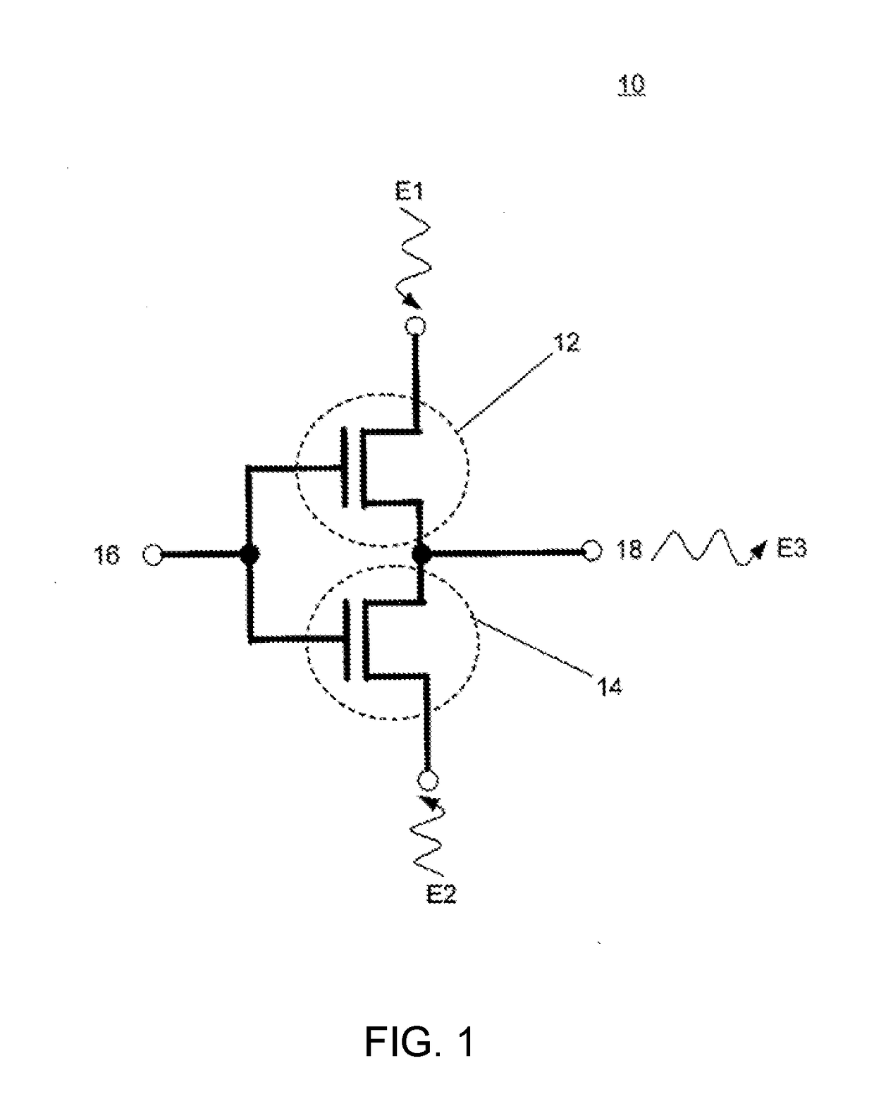
The patent text describes a method and system for using complementary plasmonic devices to create a signal controlling element. This technology can be used to build more advanced signal controlling or logic controlling devices. The complementary plasmonic circuit includes a substrate, plasmon supporting layer, and two layers of plasmonic devices with inputs and outputs. The devices can be controlled by a signal from a control gate, which affects their plasmonic properties. The method allows for the joint control of the two plasmonic devices and the generation of a complementary output using a control gate. Overall, the technology allows for more advanced and efficient signal control.

Problems solved by technology

However, since this field is nascent in many respects, there are not yet any basic components using plasmonics that can function as a building blocks for more advanced devices or systems, particularly for logic operations.

Method used


Image

  • Complementary Plasmonic Device and Method
  • Complementary Plasmonic Device and Method
  • Complementary Plasmonic Device and Method

Examples


Embodiment Construction

[0013]The claimed subject matter is now described with reference to the drawings, wherein like-referenced numerals are used to refer to like-referenced elements throughout. In the following description, for purposes of explanation, numerous specific details are set forth in order to provide a thorough understanding of the claimed subject matter. It may be evident, however, that such subject matter may be practiced without these specific details.

[0014]In brief overview, rather than modulating a quantum of light (a photon), a plasmon, or collective excitation in the electron density of a material, can be used for signal control. One can control the resonance of the surface plasmon by varying the effective dielectric constant of the constituent material. From first principles, one may couple light into a thin layer of metal at a metal-dielectric interface to form a surface plasmon under specific coupling conditions, given by:

ksp=k(ɛmɛdɛm+ɛd)1 / 2=ωcɛdsinθ

where ksp is the wave number of t...


PUM


Abstract

Methods and devices for a plasmonic circuit are described. A planar plasmonic device is configured with a controlling gate structure and when coupled to a complementary plasmonic device, a switching circuit can be realized. Also, by varying the properties of the complementary plasmonic device, the circuit can also operate as an amplifier. By use of combinations of this plasmonic circuit element, more advanced circuits and logic functions can be arrived at.

Description

[0001]This application is a divisional application of U.S. patent application Ser. No. 12 / 100,512, filed Apr. 10, 2008 by Joanna Ptasinski et al., for an invention entitled “Complementary Plasmonic Device and Method”. The '512 application is assigned to the same assignee as the present invention.FEDERALLY-SPONSORED RESEARCH AND DEVELOPMENT[0002]This (Navy Case No. 108500) is assigned to the United States Government and is available for licensing for commercial purposes. Licensing and technical inquiries may be directed to the Office of Research and Technical Applications, Space and Naval Warfare Systems Center, San Diego, Code 2112, San Diego, Calif., 92152; voice 619-553-2778; email T2@spawar.navy.mil.BACKGROUND OF THE INVENTIONField[0003]This disclosure is related to plasmonics. More particularly, this disclosure is related to surface plasmon devices configured to form a signal controlling structure.Background[0004]Plasmonics is a field where one exploits the short wavelength of a...

Claims


Application Information

Patent Timeline
Patent Type & AuthorityApplications(United States)
IPC IPC(8): G02B6/122
CPCG02B6/1226G02B6/124G02B2006/12107
InventorPTASINSKI, JOANNARUSSELL, STEPHEN
OwnerTHE UNITED STATES OF AMERICA AS REPRESENTED BY THE SECRETARY OF THE NAVY