Optical apparatus

a technology of optical equipment and optical display, which is applied in the field of optical equipment, can solve the problems of difficult manufacturing, difficult installation, and limited arrangement form of the display module (device), and achieve the degree of freedom for the number of installation and installation positions of the reflective unit and the display unit to be remarkably improved

Active Publication Date: 2018-10-11
LETINAR CO LTD
View PDF8 Cites 12 Cited by
  • Summary
  • Abstract
  • Description
  • Claims
  • Application Information

AI Technical Summary

Benefits of technology

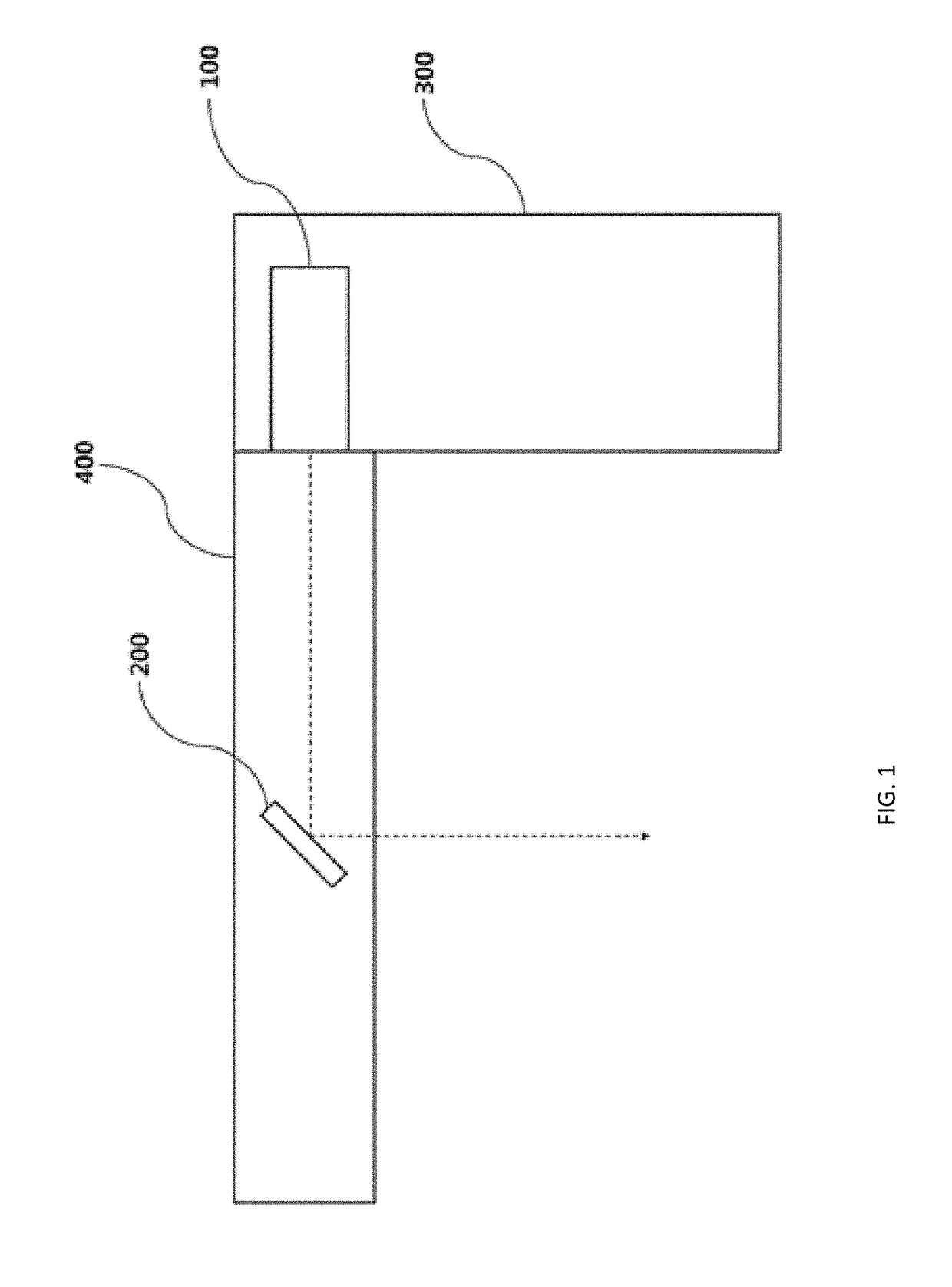
[0013]The present invention is disclosed to solve the above-described problems and necessities. An object of the present invention is to provide an optical apparatus, in which the reflective unit for reflecting the image outputted from the display unit is miniaturized, so that the number of reflective unit and the available range of the arrangement are increased, and the number of the display unit and the available range of the arrangement are increased, and simultaneously, an image having a deep depth of field can be provided to the user.
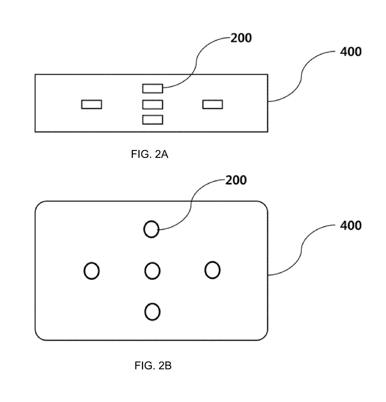
[0028]Due to the above configuration, the optical apparatus according to the present invention is configured to miniaturize the reflective unit, so that the number of the reflective unit and the available range of the arrangement are increased, and the number of the display unit and the available range of the arrangement can be increased. In other words, according to the present invention, the degree of freedom for the number of installation and installation position of the reflective unit and the display unit can be remarkably improved.
[0029]In addition, according to the optical apparatus of the present invention, the entire configuration of the optical apparatus can be remarkably simplified due to the above configuration. In addition, the weight of the optical apparatus can be lighter, the volume can be smaller, and manufacturing costs can be reduced.
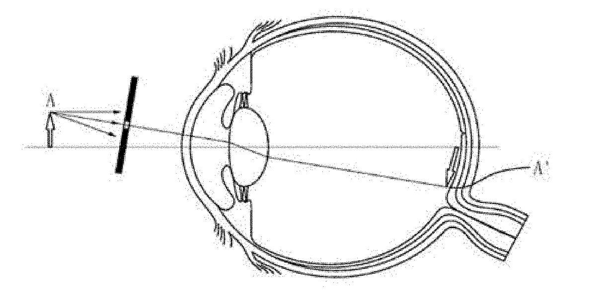
[0030]In addition, the optical apparatus according to the present invention can provide an image having a deep depth of field to the user. Accordingly, when the user look at the real world, a clear image can be always obtained regardless of the focal distance even if the user adjusts the focal distance.
[0031]In addition, the optical apparatus according to the present invention enables the user to obtain a clear image regardless of the user's eyesight due to the above configuration.

Problems solved by technology

In order to realize the above AR, the HMD is mainly used, however, a lens module (an optical system module) of the HMD has a problem in that it is very difficult to manufacture due to its complicated structure, and the lens module has a large size and heavy weight due to the complicated structure.
Due to the above structural problems, the conventional apparatus for implementing the augmented reality including ‘Patent Document 1’ and ‘Patent Document 2’ has a problem that the number of lens modules, the arrangement form of the lens module, and the arrangement form of the display module (device) are very limited.
In addition to the above problem, there is a problem in that the conventional lens module fails to provide the user with a constantly clear virtual screen although the conventional apparatus for implementing the augmented reality has a complicated structure.
However, the focus adjustment refers to that the user adjusts the focus and focuses on (fixes) one of views at which the user mainly looks, and it totally fails to solve the problem pointed out above in that the user obtains the unclear virtual screen when changing the focal distance while gazing at the real world.
The augmented reality system and the method of providing the improved focus of Patent Document 4 totally fail to solve the above problems in view of a physical scheme.
Because an additional processor is required to determine the current user focus area and additional software is required to control the processor, the software and processor may have malfunctions and errors.
Further, the manufacturing cost is high due to the additional installation of the processor and software.

Method used


Image

  • Optical apparatus
  • Optical apparatus
  • Optical apparatus

Examples


Embodiment Construction

[0039]The following detailed description of the invention refers to the accompanying drawings for illustrating specific embodiments by way of example in which the invention may be carried out. The embodiments are described in detail enough to enable those skilled in the art to carry out the invention. It should be understood that the various embodiments of the present invention may be different from each other but does not need to be mutually exclusive. For example, the particular shapes, structures, and features described herein may be embodied in other embodiments without departing from the idea and scope of the invention in connection with one embodiment. In addition, it should be understood that the location or arrangement of an individual element within each disclosed embodiment may be modified without departing from the idea and scope of the present invention. Accordingly, the following detailed description is not intended to disclose a limited meaning, and the scope of the in...


PUM


Abstract

The present invention relates to an optical apparatus with a wide available range of a lens module, which is capable of providing an image having a deep depth of field to a user. The optical apparatus according to the present invention includes a display unit for outputting an image; at least one reflective unit having a size of 4 mm or less for reflecting the image outputted from the display unit; and a frame unit fixed thereto with the display unit and the at least one reflective unit.

Description

BACKGROUND OF THE INVENTION1. Field of the Invention[0001]The present invention relates to an optical apparatus using reflection, refraction, or diffraction, and more specifically, to an optical apparatus for providing an image with a deep depth of field to a user and having a wide available range of an optical module included in the optical apparatus.2. Description of the Related Art[0002]An augmented reality (AR) is a technology for enabling a user to see a virtual screen (virtual world) superimposing a real world which the user sees with eyes. The AR has been called a mixed reality in the early stage because a single image is displayed by combining the real world with the virtual world having additional information in real time.[0003]The AR has begun to be studied starting with the development of a see-through head mounted display (HMD), the AR has a meaning different from a virtual reality (VR). Whereas the user cannot see the actual environment because the VR leads the user to ...

Claims


Application Information

Patent Timeline
Patent Type & Authority Applications(United States)
IPC IPC(8): G02B27/01G02B27/00G02B17/00
CPCG02B27/0172G02B27/0075G02B27/0149G02B17/006G02B27/0179G02B2027/0127G02B2027/0185G02B27/0101G02B2027/0138G06T19/006G02B30/35G06T19/00
Inventor HA, JEONG HUN
Owner LETINAR CO LTD
Why Eureka
Try Eureka