Multi-mode wireless power transmission method and device for same

Active Publication Date: 2018-10-11
SCRAMOGE TECH LTD
View PDF8 Cites 22 Cited by
  • Summary
  • Abstract
  • Description
  • Claims
  • Application Information

AI Technical Summary

Benefits of technology

[0040]The method and device according to the embodiments have the following effects.
[0041]The present embodiment has the advantage of providing a multimode wireless power transmission method and apparatus therefor that are capable of minimizing power loss.
[0042]The present embodiment also relates to a multi-mode wireless power transmission method capable of adaptively blocking mutual interference between a transmission induction coil and a transmission resonant coil in a wireless power transmission device supporting both an electromagnetic induction system and an electromagnetic resonance system.
[0043]In addition, the present embodiment has an advantage of providing a wireless power transmission device provided with a parallel LC

Problems solved by technology

Accordingly, power supply to these devices or sensors is becoming a new challenge.
In addition, as the types of mobile devices such as Bluetooth handsets and iPods, as well as mobile phones, rapidly increase in number, charging the battery has required time and effort for users.
However, this scheme may be used only at a limited distance and in a limited space, and has somewhat low e

Method used


Image

  • Multi-mode wireless power transmission method and device for same
  • Multi-mode wireless power transmission method and device for same
  • Multi-mode wireless power transmission method and device for same

Examples


Embodiment Construction

[0067]Hereinafter, an apparatus and various methods to which embodiments of the present disclosure are applied will be described in detail with reference to the drawings. As used herein, the suffixes “module” and “unit” are added or used interchangeably to facilitate preparation of this specification and are not intended to suggest distinct meanings or functions.

[0068]In the description of the embodiments, it is to be understood that when an element is described as being “on” or “under” another element, it can be “directly” on or under another element or can be “indirectly” formed such that one or more other intervening elements are also present between the two elements. In addition, when an element is described as being “on” or “under,” the term “on” or “under” may refer to not only the upper side but also the lower side with respect to the element.

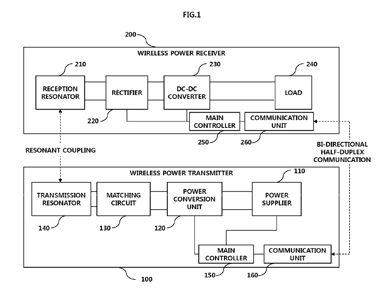
[0069]In the description of the embodiments, “wireless power transmitter,”“wireless power transmission device,”“transmission terminal,”...


PUM


Abstract

The present invention relates to a multi-mode wireless power transmission method and a device for the same. A wireless power transmitter for supporting a plurality of wireless power transmission modes, according to one embodiment of the present invention, can comprise: a first transmitter for transmitting a first power signal corresponding to a first wireless power transmission mode; a second transmitter for transmitting a second power signal corresponding to a second wireless power transmission mode; and a first power cutoff circuit coupled to the first transmitter so as to block the incoming second power signal and allow the first power signal to pass therethrough. Therefore, the present invention can minimize power consumption in the wireless power transmitter supporting the plurality of wireless power transmission modes, and can maximize power transmission efficiency.

Description

TECHNICAL FIELD[0001]Embodiments relate to wireless charging technology, and more particularly, to a multi-mode wireless power transmission method capable of minimizing power loss caused by mutual interference between an induction coil and a resonant coil in a wireless power transmission device that supports both inductive and resonant wireless power transmission schemes and a device for the same.BACKGROUND ART[0002]Recently, as information and communication technology rapidly develops, a ubiquitous society based on information and communication technology is being formed.[0003]In order for information communication devices to be connected anywhere and anytime, sensors equipped with a computer chip having a communication function should be installed in all facilities throughout the society. Accordingly, power supply to these devices or sensors is becoming a new challenge. In addition, as the types of mobile devices such as Bluetooth handsets and iPods, as well as mobile phones, rapi...

Claims


Application Information

Patent Timeline
IPC IPC(8): H02J50/70H02J50/40H02J50/12H02J50/90H02J50/80H02J7/02
CPCH02J50/70H02J50/40H02J50/12H02J50/90H02J50/80H02J7/025H02J50/10H02J50/402
Inventor BAE, SU HO
Owner SCRAMOGE TECH LTD
Why Eureka
Try Eureka