Sliding linear internal combustion engine

Inactive Publication Date: 2018-10-25
DAVIS GLOBAL ENGINES LLC
View PDF5 Cites 0 Cited by
  • Summary
  • Abstract
  • Description
  • Claims
  • Application Information

AI Technical Summary

Benefits of technology

The present invention provides an improved internal combustion engine with better thermal efficiency, more confined combustion and expansion volume, and requires less fuel to produce a given amount of torque without increasing exhaust gas temperature. The engine includes an exhaust valve and at least one intake port for releasing combustion byproducts and allowing air to enter the cylinder for combustion. The swept volume of the piston in the cylinder after combustion increases more slowly as compared to an internal combustion engine with a piston rod connected directly to the crankshaft.

Problems solved by technology

Internal combustion engines typically have a thermal efficiency ranging from 15% to 40%, which results in significant emissions of waste heat, unburned fuel, particulates, and pollutants resulting from inefficient and incomplete combustion.
The majority of the fuel's energy content is lost in the form of hot exhaust gas.
Internal combustion engines of the prior art are limited in power produced per unit of engine displacement by the maximum safe operating range of exhaust gas temperature.
Moreover, conventional internal combustion engines yield incomplete combustion, resulting in decreased thermal efficiency and increased emissions of particulates, raw fuel, and various chemical compounds resulting from a portion of the fuel introduced undergoing incomplete chemical reaction during combustion.

Method used


Image

  • Sliding linear internal combustion engine
  • Sliding linear internal combustion engine
  • Sliding linear internal combustion engine

Examples


Embodiment Construction

)

[0035]In describing the embodiments of the present invention, reference will be made herein to FIGS. 2-12 of the drawings in which like numerals refer to like features of the invention.

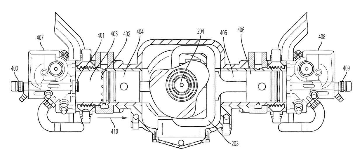
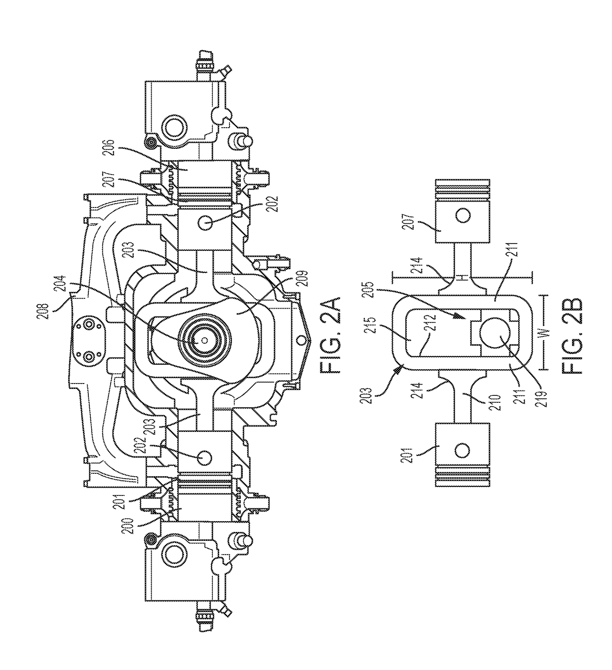
[0036]The present invention relates to an improved internal combustion engine or High Efficiency Sliding Linear Internal Combustion Engine (hereinafter referred to as the “SLIC Engine”), comprising an engine and rotating assembly wherein the piston motion relative to crankshaft motion results in a substantially smaller swept volume throughout combustion and hot gas expansion processes while retaining the same total displacement, thereby providing a comparatively more confined combustion and expansion volume resulting in higher mean effective pressure given the same amount of fuel.

[0037]Certain terminology is used herein for convenience only and is not to be taken as a limitation of the invention. For example, words such as “top,”“bottom,”“upper,”“lower,”“left,”“right,”“horizontal,”“vertical,”“upward,...


PUM


Abstract

An internal combustion engine comprising a crankshaft rotatable about an axis, one or more pairs of cylinders opposed from each other on either side of the crankshaft, one or more pairs of pistons alternately moveable within the cylinders by combustion therein, and a common rod connecting the pair of pistons, the pistons and common rod being linearly slideable in a first direction. A linear bearing is disposed on the common rod between the pair of pistons and connects the common rod to the crankshaft, the linear bearing being slideable in a second direction normal to the first direction. As the pair of pistons alternately move within the cylinders, the crankshaft is driven by movement of the common rod and pair of pistons back and forth in the first direction and movement of the linear bearing back and forth in the second direction.

Description

RELATED APPLICATIONS[0001]This application is a U.S. National Stage application under 35 U.S.C. § 371(c) of international PCT Application No. PCT / US2017 / 055125, filed Oct. 4, 2017, which claims priority to U.S. Patent Application No. 62 / 404,107, filed Oct. 4, 2016, and U.S. Patent Application No. 62 / 403,900, filed Oct. 4, 2016, the entire disclosures of which are incorporated herein by reference.BACKGROUND OF THE INVENTION1. Field of the Invention[0002]This invention relates generally to internal combustion engines, and more specifically, to an improved internal combustion engine providing a smaller swept volume throughout combustion and expansion while retaining the same total displacement over that of internal combustion engines of the prior art.2. Description of Related Art[0003]Internal combustion engines typically employ one or more pistons each coupled to a crankshaft by a connecting rod, each connecting rod having two pivot points to couple linear piston motion to rotational ...

Claims


Application Information

Patent Timeline
IPC IPC(8): F02B75/24
CPCF02B75/24F02B2075/025F01B1/08F01B9/023F02B75/32
Inventor DAVIS, COREY M.
Owner DAVIS GLOBAL ENGINES LLC
Why Eureka
Try Eureka