X-ray tube
- Summary
- Abstract
- Description
- Claims
- Application Information
AI Technical Summary
Benefits of technology
Problems solved by technology
Method used
Image

Examples
embodiment 1
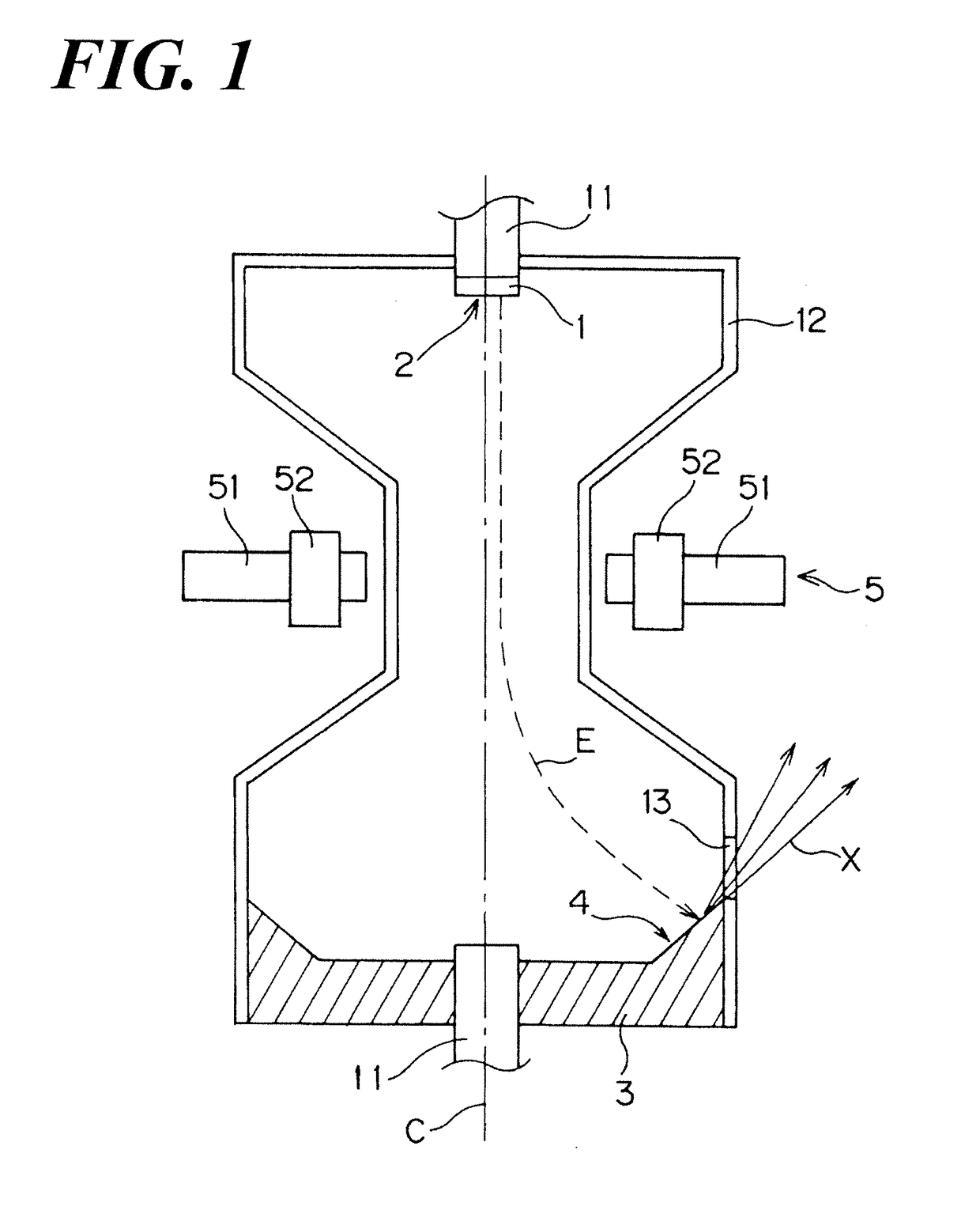
[0050]Various operations may be described as multiple discrete operations in turn, in a manner that may be helpful in understanding embodiments of the present invention; however, the order of description should not be construed to imply that these operations are order dependent.[0051]The inventor sets forth Embodiments of the present invention based on the following FIGs. FIG. 1 is a schematic diagram illustrating the rotating envelope X-ray tube according to the aspect of the present invention,
[0052]Such rotating envelope X-ray tube comprises an envelope 12 of which inside is a vacuum The envelope 12 rotates around the center of axis of a pair of rotation axes 11 as the rotation center by a motor, not shown in FIG. In addition, the cathode 1 comprising the emitter 2 having the tabular electron beam emission surface is installed at the tip location of the one of the rotation axes 11 inside the envelope 12. In addition, the anode 3 having the target surface 4 that emits an X-ray when...
embodiment 2
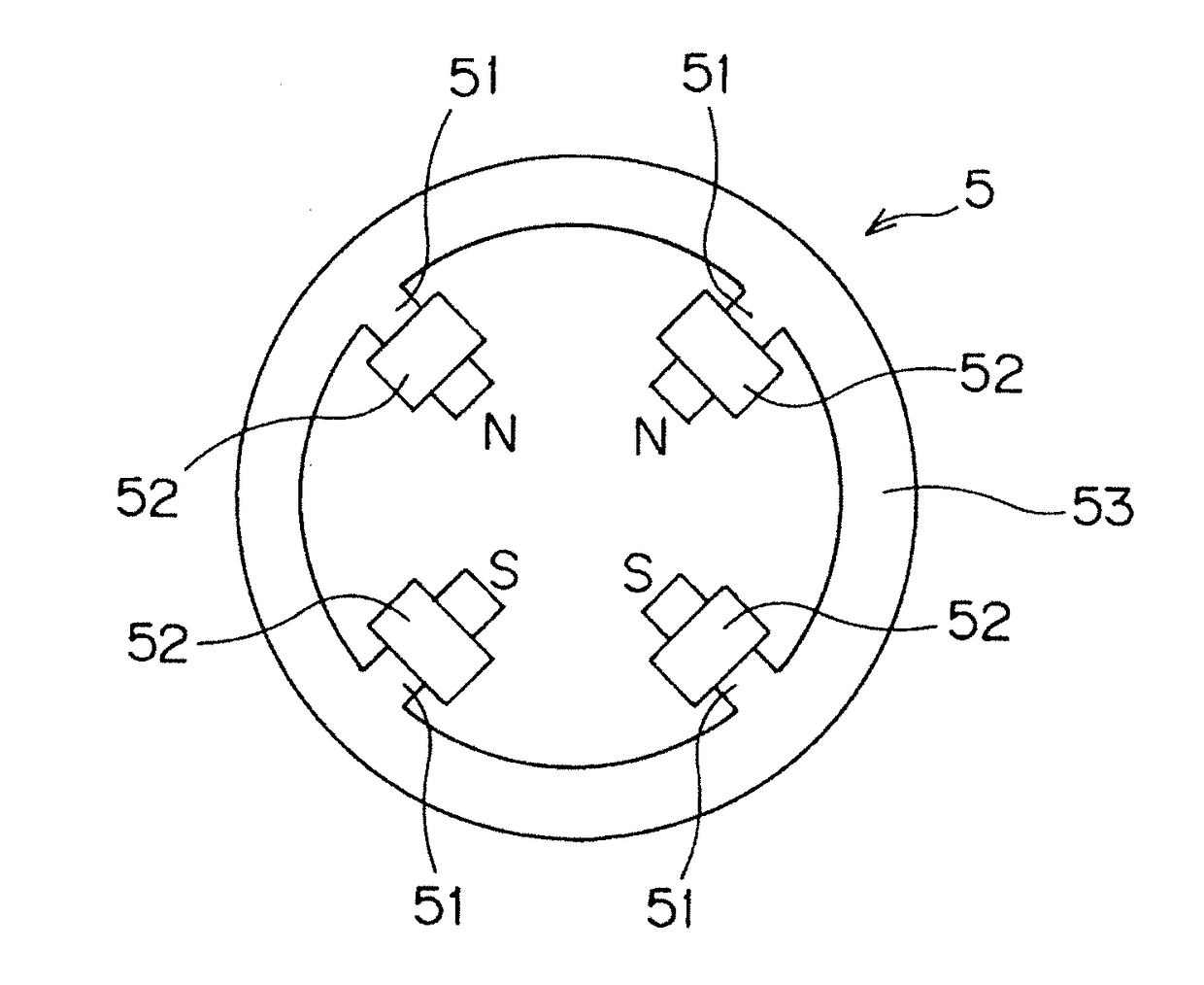
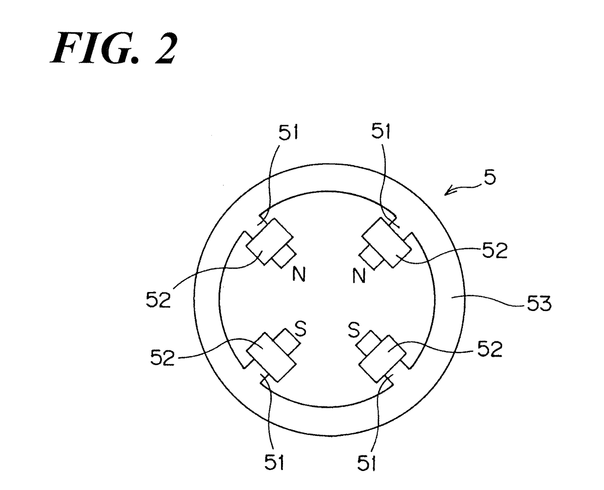
[0072]A rotating envelope X-ray tube, according to the aspect of the Embodiment 2, comprises a quadrupole lens, which consists of a pair of quadrupoles 6, between the cathode 1 and the magnetic field generator 5.
[0073]FIG. 10 is a schematic front view of the quadrupole 6 forming the quadrupole lens.
[0074]Such quadrupole 6 comprises four protrusions 61, which are formed at even intervals relative to the circular yoke 63, and each coil 62 winding each protrusion 61. Relative to such quadrupole 6, the four protrusions 61 and the four coils 62 generate alternately the N-pole and the S-pole. In such way, the quadrupole lens is formed by placing a pair of quadrupoles in the state of that quadrupoles 6 are distant at a constant distance and the polarity thereof are reversed, and the electric current that is provided the coil 62 therewith is controlled, so that the diameter of the electron beam passes through the quadrupole lens can be controlled. Accordingly, the diameter of the electron b...
embodiment 3
[0082]Relative to the rotating envelope X-ray tube according to the aspect of the Embodiment 3, the diameter of the electron beam E emitted from the emitter 2 of the cathode 1 is narrowed down by the quadrupole lens consisting of the quadrupoles 6 and the quadrupole function due to the composite members 7. And the electron beam E is deflected by the magnetic field generator of the composite member 7 and then collides with the target surface 4 of the anode 3.
[0083]Now, relative to the rotating envelope X-ray tube according to the aspect of the Embodiment 3, the function of the quadrupole lens consisting of the quadrupoles 6 and the composite members 7 is operative at the cathode 1 side and the function of the magnetic field generation is operative in the anode 3 side. Therefore, as well as the aspect of the Embodiment 2, the inside opening relative to the quadrupole 6 is formed larger, so that any possibly occurring issue can be avoided. In addition, the single composite member 7 is ...
PUM
 Abstract
Description
Claims
Application Information
 - R&D Engineer
- R&D Manager
- IP Professional
- Industry Leading Data Capabilities
- Powerful AI technology
- Patent DNA Extraction
Browse by: Latest US Patents, China's latest patents, Technical Efficacy Thesaurus, Application Domain, Technology Topic.
© 2024 PatSnap. All rights reserved.Legal|Privacy policy|Modern Slavery Act Transparency Statement|Sitemap