Image processing apparatus and image processing method

Active Publication Date: 2018-10-25
FUJIFILM CORP
View PDF5 Cites 3 Cited by
  • Summary
  • Abstract
  • Description
  • Claims
  • Application Information

AI Technical Summary

Benefits of technology

The patent describes a method for improving the resolution of images captured using a camera. The method involves performing a coordinate transformation on the image data to correct any distortion caused by the camera's optical system. The transformed image data is then used to create a restored image that is close to the original object image. The method can be used to enhance the resolution of images captured in various imaging conditions. The technical effect of this patent is to improve the quality of images captured using a camera and to correct any distortion caused by the optical system.

Problems solved by technology

However, in the technique according to the related art, it is difficult to effectively obtain a high-quality restored image in a case in which the resolution of the imaging lens varies depending on the direction or in a case in which distortion occurs.
Therefore, the process is complicated and it is difficult to perform the process at a high speed.
As a result, the restoration process is complicated and it is difficult to perform the process at a high speed.
The technique is not very effective.
The technique disclosed in JP2010-087672A has the problem that it is necessary to convert the filter used for the restoration process according to the distortion correction conditions.

Method used


Image

  • Image processing apparatus and image processing method
  • Image processing apparatus and image processing method
  • Image processing apparatus and image processing method

Examples


first embodiment

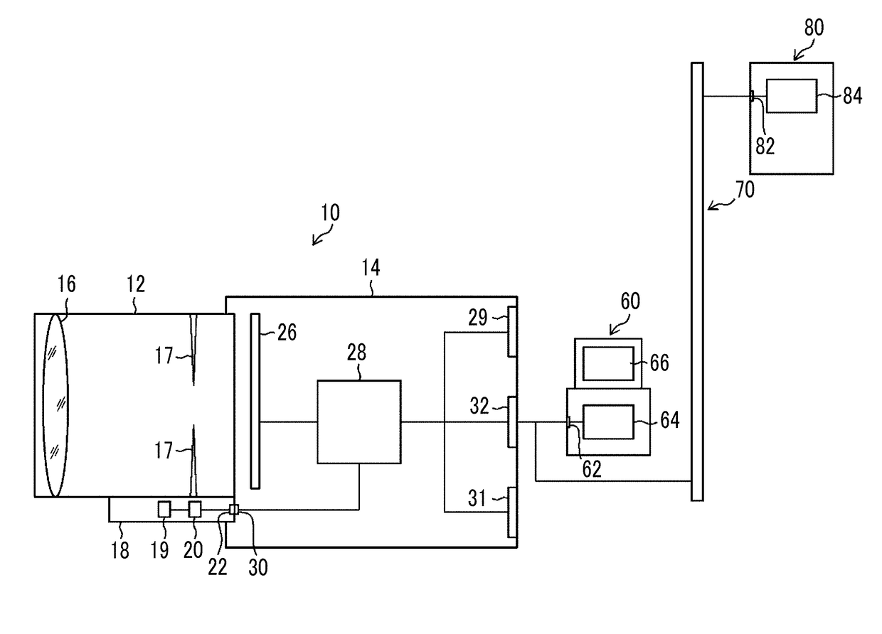
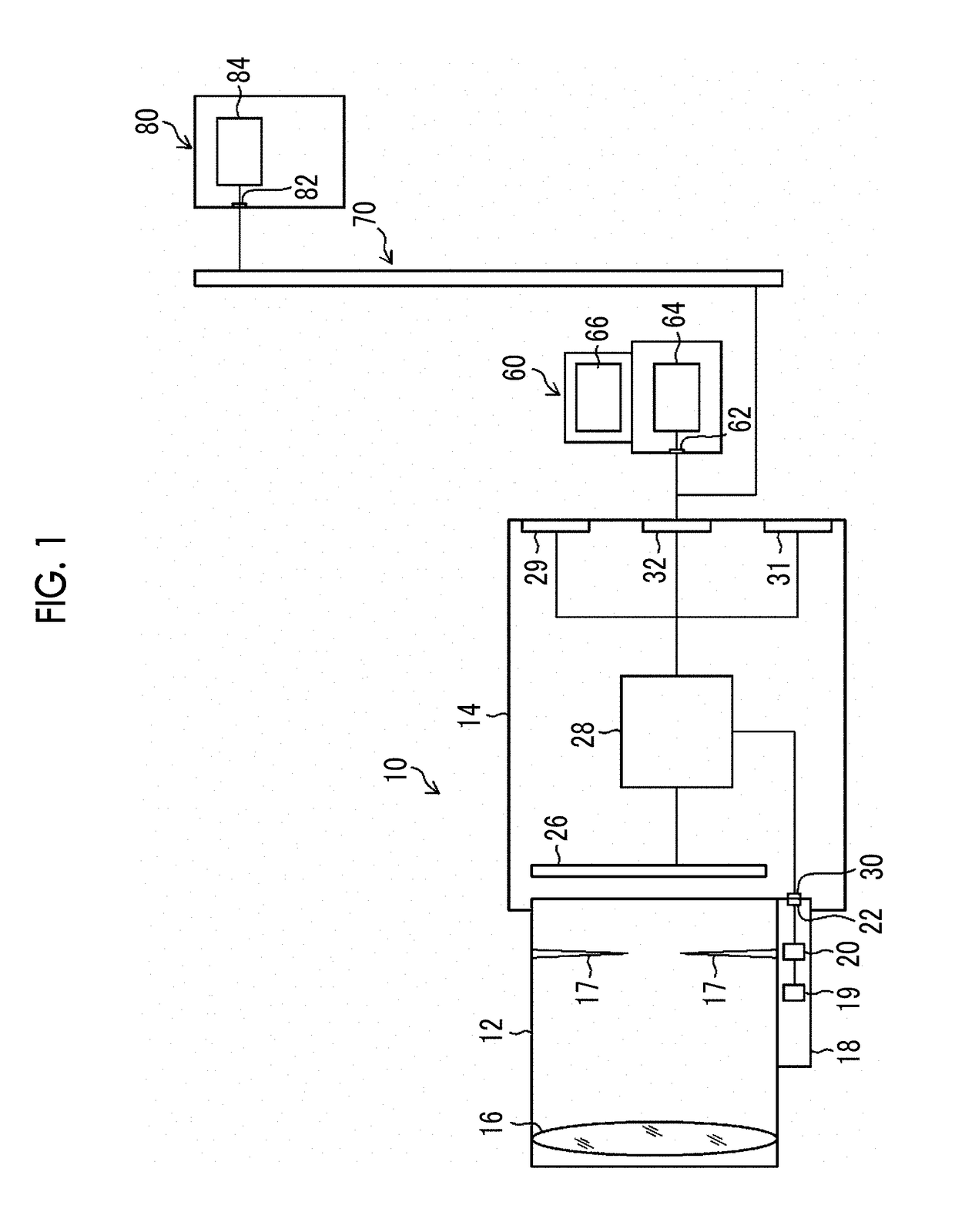
[0048]In a first embodiment, a case in which the invention is applied to a digital camera (image processing apparatus) that can be connected to a computer will be described. FIG. 1 is a block diagram illustrating a digital camera 10 connected to a computer.

[0049]

[0050]The digital camera 10 includes a lens unit 12 and a camera body 14 including an imaging element 26. The lens unit 12 and the camera body 14 are electrically connected to each other through a lens unit input / output unit 22 of the lens unit 12 and a camera body input / output unit 30 of the camera body 14. The digital camera 10 can be used in various fields. For example, the digital camera 10 can be used in a security field (surveillance camera) or a medical field (endoscope) in addition to a general imaging field.

[0051]The lens unit 12 includes an optical system including, for example, an imaging lens 16 and a stop 17 and an optical system operation unit 18 that controls the optical system. The optical system operation un...

example 1

[0067]

[0068]FIG. 4A is a diagram schematically illustrating an object 50. FIG. 4B is a diagram schematically illustrating the captured image 51 acquired by the image acquisition unit 40 in a case in which the digital camera 10 captures the image of the object 50. The image acquisition unit 40 transmits the acquired captured image 51 to the coordinate transformation unit 41. In the captured image 51 illustrated in FIG. 4B, the tangential direction of the imaging lens 16 (a radial direction of circumference having the optical axis as the center) is represented by Ta and the sagittal direction of the imaging lens 16 (a direction tangent to the circumference having the optical axis as the center; a direction perpendicular to the radial direction) is represented by Sa. In FIGS. 4A to 4C, FIGS. 13A to 13C, and FIG. 15, characters “FUJIFILM Value from Innovation” are a registered trademark.

[0069]

[0070]In addition, the captured image 51 depends on the resolution of the imaging lens 16 and h...

example 2

[0103]Next, a case in which the relationship between the sagittal resolution S and the tangential resolution T is different from that in Example 1 will be described. In Example 1, the case in which the sagittal resolution S is higher than the tangential resolution T as illustrated in FIG. 5 has been described. In Example 2, on the contrary, a case in which the tangential resolution T is higher than the sagittal resolution S in the captured image will be described. FIG. 14 is a diagram illustrating resolutions in the case. In this case, it is assumed that the captured image 53 has barrel distortion (distortion is negative) as illustrated in FIG. 15. In Example 2, the configuration of the digital camera 10 and the procedure of a process may be the same as those in Example 1.

[0104]In a case in which the captured image 53 has the characteristics illustrated in FIG. 14 and FIG. 15, a coordinate transformation process for increasing the sagittal resolution S (compressing a central portion...


PUM


Abstract

An image processing apparatus includes an image acquisition unit that acquires a captured image of an object captured through an imaging lens, a coordinate transformation unit that performs coordinate transformation for the captured image such that a sagittal resolution in a direction tangent to circumference having a center of an imaging surface as an origin and a tangential resolution in a radial direction perpendicular to the tangential direction are close to each other at a designated spatial frequency, and a resolution enhancement processing unit that performs a rotationally-symmetric resolution enhancement process for the coordinate-transformed image. According to this aspect, a rotationally-symmetric filter can be used for the resolution enhancement process. It is possible to prevent an increase in filter size or to perform a process at a high speed. It is possible to prevent a process from being complicated due to the use of the filter for coordinate transformation.

Description

CROSS-REFERENCE TO RELATED APPLICATIONS[0001]The present application is a Continuation of PCT International Application No. PCT / JP2016 / 083698 filed on Nov. 14, 2016 claiming priority under 35 U.S.C § 119(a) to Japanese Patent Application No. 2015-246228 filed on Dec. 17, 2015. Each of the above applications is hereby expressly incorporated by reference, in their entirety, into the present application.BACKGROUND OF THE INVENTION1. Field of the Invention[0002]The present invention relates to an image processing apparatus and an image processing method that process an image acquired by an optical system, and more particularly, to an image processing apparatus and an image processing method that perform image processing corresponding to the characteristics of the optical system.2. Description of the Related Art[0003]In some cases, the resolution of an image captured through an optical system is reduced due to the characteristics of the optical system and image processing (resolution enh...

Claims


Application Information

Patent Timeline
IPC IPC(8): H04N5/232G06T5/00
CPCH04N5/23235G06T5/006G06T5/003G06T2207/20024G06T2207/20192G06T5/20G06T2207/10024G06T3/4053H04N23/81H04N23/815H04N25/615G06T5/80G06T5/73
Inventor KISHINE, YASUNOBU
Owner FUJIFILM CORP
Why Eureka
Try Eureka