
Imaging apparatus, photographic lens unit, and imaging unit

Active Publication Date: 2012-10-04
KYOCERA CORP
View PDF4 Cites 2 Cited by
  • Summary
  • Abstract
  • Description
  • Claims
  • Application Information

AI Technical Summary

Benefits of technology

[0013]In an imaging apparatus according to the present invention having a configuration as described above, it is possible to reduce a noise generated in an image obtained by regularly dispersing light beams of a subject image, capturing a dispersed image, and reducing blur from the captured image.

Problems solved by technology

However, increasing the F-number leads to an insufficient amount of light of a subject optical image being received by a light receiving surface.
However, decreasing the shutter speed leads to a difficulty in capturing a moving subject.
Further, increasing the ISO sensitivity causes problems such as increased noise in a captured image.
However, according to the inventions disclosed in Patent Documents 1 and 2, the response of the optical transfer function of the optical imaging system by the phase mask was low.
Consequently, there was a problem in that performing a restoration processing operation so as to sufficiently reduce the blur resulted in increased noise.

Method used


Image

  • Imaging apparatus, photographic lens unit, and imaging unit
  • Imaging apparatus, photographic lens unit, and imaging unit
  • Imaging apparatus, photographic lens unit, and imaging unit

Examples


Embodiment Construction

[0022]Hereinafter, an embodiment of a lens unit and an imaging apparatus adopting the present invention will be described with reference to the drawings.

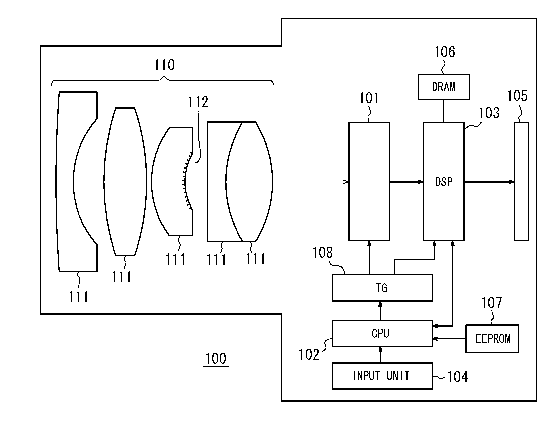
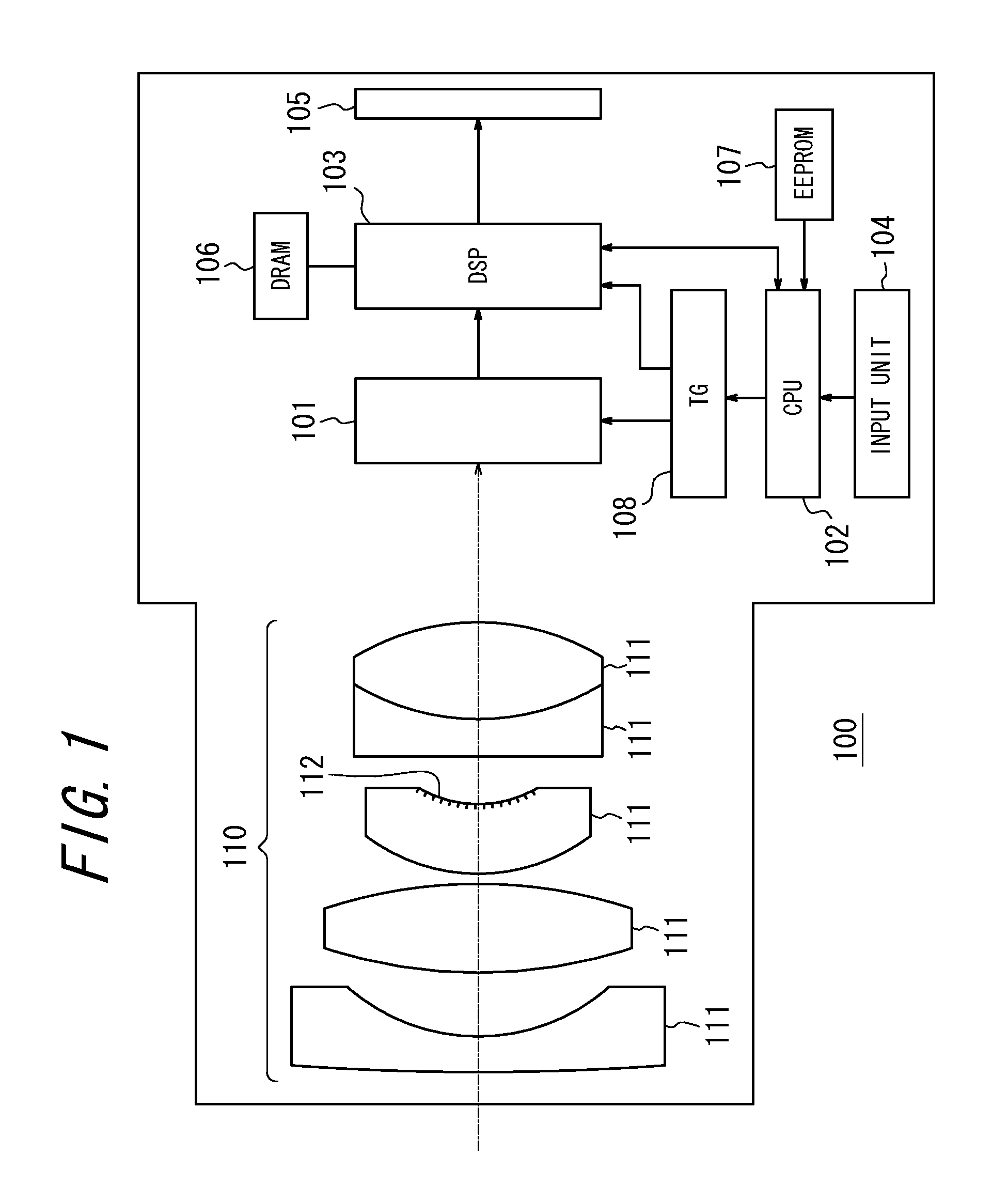
[0023]FIG. 1 is a block diagram illustrating an optical configuration and an electrical schematic configuration of a digital camera as an imaging apparatus according to an embodiment of the present invention.

[0024]The digital camera 100 comprises an optical imaging system 110, an image sensor 101, a CPU 102, a DSP 103, an input unit 104, a monitor 105, and so on.

[0025]The optical imaging system 110 includes a plurality of lenses 111. One of the lenses 111 has an aberration control surface 112 formed on an inner surface thereof so as to generate a spherical aberration in the optical imaging system 110. In order to satisfy optical characteristics as described below, the aberration control surface 112 is formed rotationally symmetric with respect to an optical axis. The optical imaging system 110 forms a subject image to be captured, w...


PUM


Abstract

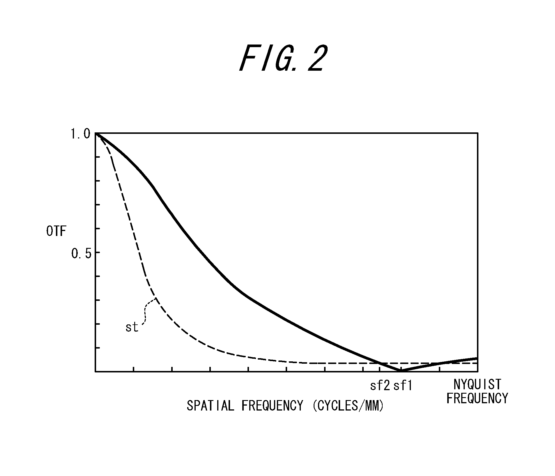
An imaging apparatus comprises an optical imaging system 110, an image sensor 101, and an image processor 103. The optical imaging system 110 has an aberration control element 103 for generating a predetermined aberration. The optical imaging system 110 forms an optical image. The image sensor 101 generates an image signal corresponding to the optical image. The image processor 103 performs image processing on the image signal so as to enhance a degraded image characteristic on the basis of the predetermined aberration. The aberration control element 112 causes a response of an optical transfer function of the optical imaging system 110 to be zero at a first spatial frequency. The first spatial frequency is below a Nyquist frequency of the image sensor 201.

Description

CROSS-REFERENCE TO RELATED APPLICATION[0001]This application claims priority to Japanese Patent Application Nos. 2011-082007, filed on Apr. 1, 2011, the contents of which are incorporated herein by reference in their entireties.TECHNICAL FIELD[0002]The present invention relates to an imaging apparatus, a lens unit and an imaging unit, which allows increasing a depth of field.BACKGROUND ART[0003]In an imaging apparatus such as a camera and a video camera, it is desired that images of various subjects present at a wide range of distances from an optical imaging system be captured with less blur. That is to say, it is desired that a depth of field of the optical imaging system be increased. The depth of field can be increased by adjusting an aperture stop so as to increase the F-number. However, increasing the F-number leads to an insufficient amount of light of a subject optical image being received by a light receiving surface. Thus, measures must be taken, such as decreasing a shutt...

Claims


Application Information

Patent Timeline
IPC IPC(8): H04N5/217H04N5/225
CPCH04N5/3572H04N25/615
Inventor HAYASHI, YUSUKE
Owner KYOCERA CORP
Learn More