
Protective Structure For Outdoor Installation of Drive-Over Tire Inspection System

a protection structure and tire inspection technology, applied in vehicle tyre testing, measurement devices, instruments, etc., can solve the problem that outdoor installations are at greater risk of damage from improper vehicle traffi

Inactive Publication Date: 2018-11-01
HUNTER ENG
View PDF0 Cites 1 Cited by
  • Summary
  • Abstract
  • Description
  • Claims
  • Application Information

AI Technical Summary

Benefits of technology

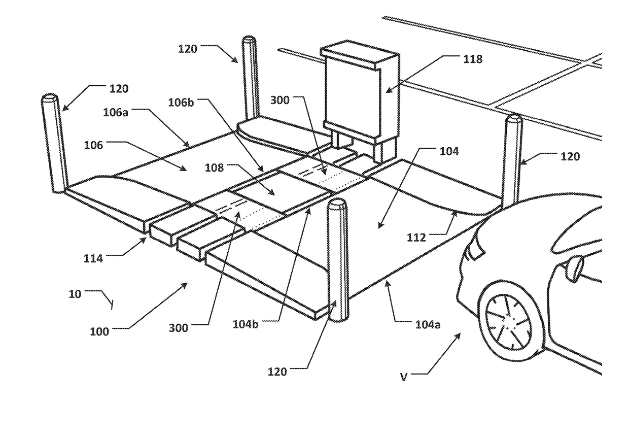
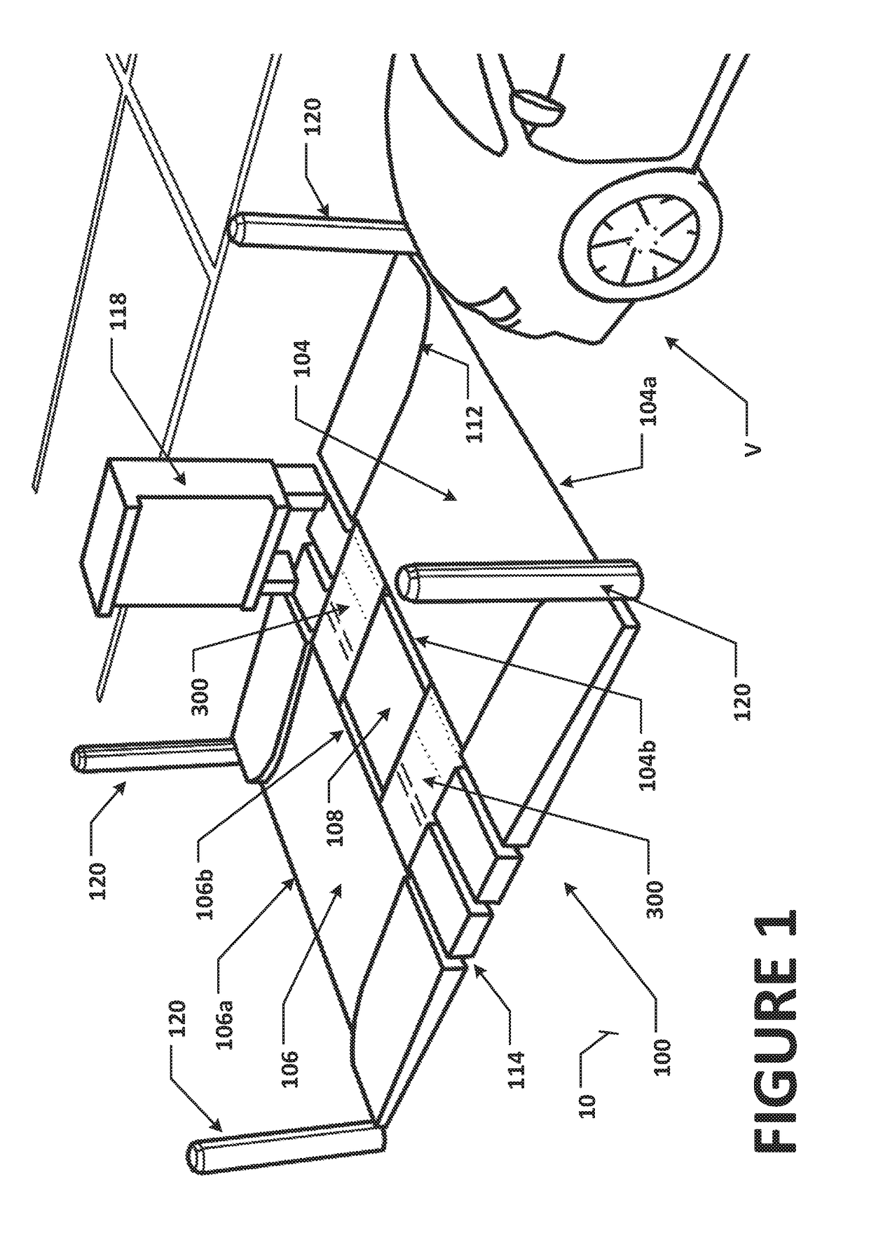
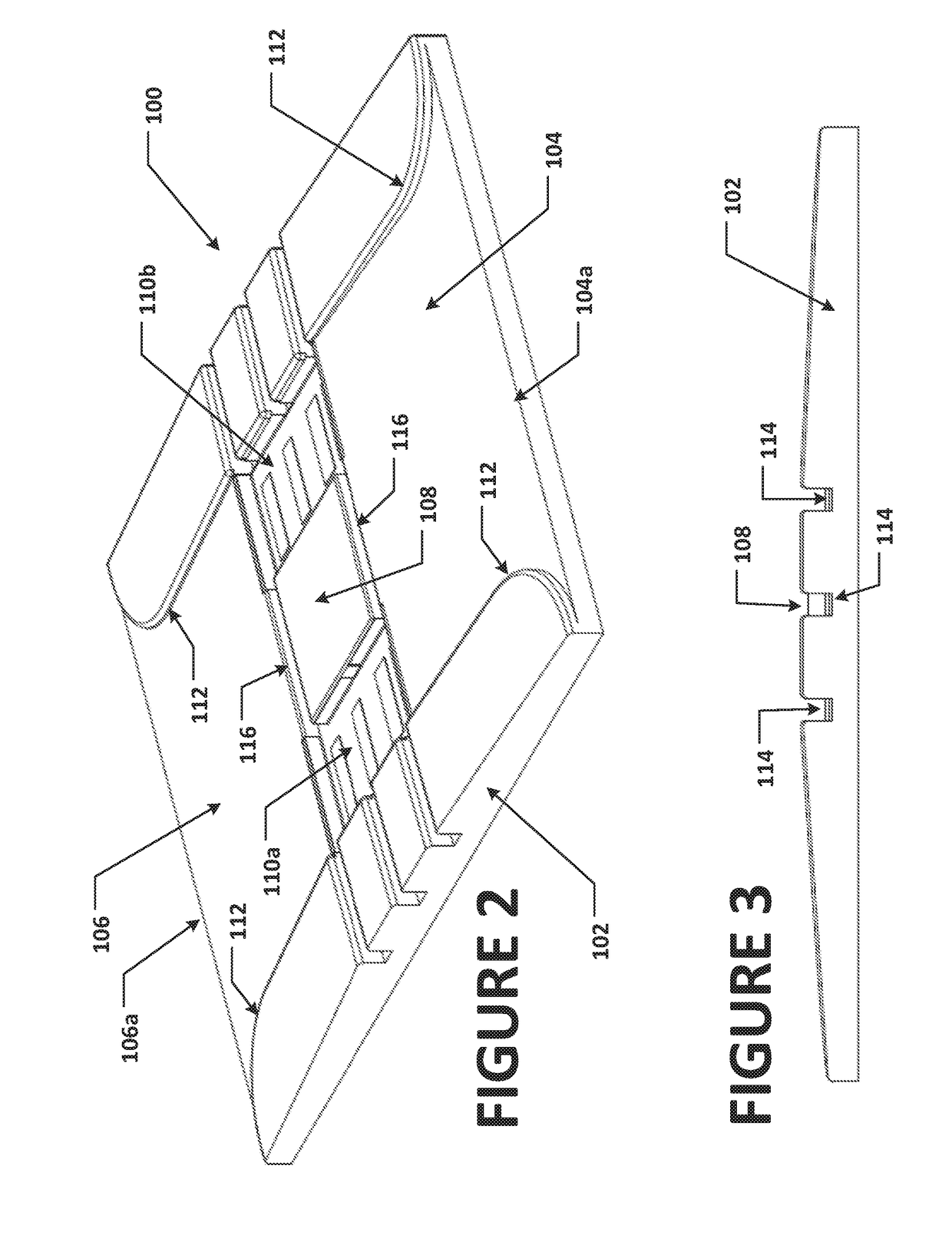
[0007]In one embodiment, the present disclosure sets forth a protective structure for an outdoor installation of a drive-over tire inspection system. The protective structure consists of a base for placement on an existing surface, such as a paved parking lot, roadway, or on a prepared surface, such as compacted gravel. The base incorporate an approach ramp and a departure ramp, vehicle guides on each side of the respective ramps, a pair of sensor receiving recesses centrally disposed between the ramps, and at least on

Problems solved by technology

However, outdoor installations are generally exposed to a wider range of environmental conditions, including flooding from rain or snow, and accumulation of debris such as dirt, leaves, and de-icing products in recessed or exposed area.
Furthermore, outdoor installati

Method used


Image

  • Protective Structure For Outdoor Installation of Drive-Over Tire Inspection System
  • Protective Structure For Outdoor Installation of Drive-Over Tire Inspection System
  • Protective Structure For Outdoor Installation of Drive-Over Tire Inspection System

Examples


Embodiment Construction

[0021]The following detailed description illustrates the invention by way of example and not by way of limitation. The description enables one skilled in the art to make and use the present disclosure, and describes several embodiments, adaptations, variations, alternatives, and uses of the present disclosure, including what is presently believed to be the best mode of carrying out the present disclosure.

[0022]Turning to the figures, and to FIGS. 1-3 in particular, a protective structure of the present disclosure for an outdoor installation of a drive-over tire inspection system is shown generally at 100. The protective structure 100 consists of a base 102 for installation on an existing surface 10, such as a paved parking lot, roadway, or on a prepared surface, such as compacted gravel. The base 102 incorporates an approach ramp 104 typically inclined upward from an outer longitudinal end 104a towards a longitudinal inner end 104b, and a departure ramp 106 typically inclined opposi...


PUM


Abstract

A protective structure for an outdoor installation of a drive-over tire inspection system. The protective structure consists of a base incorporating approach and departure ramps, vehicle guides on each side of the respective ramps, a pair of sensor receiving recesses centrally disposed between the ramps, and at least one channel for draining water from within the sensor receiving recesses. A drainage channel and a conduit for the routing of data communication cables, power cables, and trigger signal cables connects the sensor receiving recesses. Optionally, protective bollards are disposed in proximity to the corners or sides of the protective structure, guiding vehicles onto the approach and departure ramps, and to prevent vehicles from crossing over the protective structure in unintended directions.

Description

CROSS-REFERENCE TO RELATED APPLICATIONS[0001]The present application is related to, and claims priority from, co-pending U.S. Provisional Patent Application Ser. No. 62 / 490,277 filed on Apr. 26, 2017, and which is herein incorporated by reference.STATEMENT REGARDING FEDERALLY SPONSORED RESEARCH[0002]Not Applicable.BACKGROUND OF THE INVENTION[0003]The present application is related to drive-through vehicle inspection stations, and in particular, to a protective structure for an outdoor installation of a drive-over tire inspection system.[0004]Drive-through or drive-over vehicle inspection systems offer vehicle operators an opportunity to complete an inspection of one or more parameters of a vehicle without the need for the operator to leave the vehicle, stop the vehicle, or shut off the vehicle for an extended period of time while measurements of the vehicle are acquired. Drive-through or drive-over inspection systems are particularly suited for installation in areas of controlled hi...

Claims


Application Information

Patent Timeline
IPC IPC(8): G01M17/02G01B21/18
CPCG01M17/02G01B21/18
Inventor STIEFF, MICHAEL T.
Owner HUNTER ENG
Learn More