Electrode stack and battery manufacturing method

a technology of electrode stack and battery, which is applied in the direction of sustainable manufacturing/processing, wound/folded electrode electrodes, batteries, etc., can solve the problems of small contact area, difficult to realize inexpensive batteries, and increase the manufacturing cost of electrode assemblies and batteries

Active Publication Date: 2018-11-01
TOYOTA JIDOSHA KK
View PDF0 Cites 3 Cited by
  • Summary
  • Abstract
  • Description
  • Claims
  • Application Information

AI Technical Summary

Benefits of technology

[0021]In this battery manufacturing method, the average particle size of the first polyethylene particles of the first bonding layer is set to 0.3 μm to 1.0 μm, which makes it easy to handle the first polyethylene particles and to provide the first bonding layer using these first polyethylene particles. Moreover, the average particle size of the second polyethylene particles of the second bonding layer is set to 2.0 μm to 4.0 μm, which makes it easy to handle the second polyethylene particles and to provide the second bonding layer using these second polyethylene particles.

Problems solved by technology

When a high contact pressure is required to press and bond together electrode stacks placed on top of each other, it is necessary to employ a large-sized press apparatus or reduce the production rate, which tends to cause an increase in the manufacturing costs of the electrode assembly and the battery.
This makes it difficult to realize an inexpensive battery.
Conversely, when this contact pressure is lower, the first polyethylene particles undergo less deformation, resulting in a smaller contact area between the first bonding layer and the second electrode plate and in weaker bonding strength between the first bonding layer and the second electrode plate.
However, roller pressing can easily apply a larger pressing force than flat pressing to the band-shaped composite body and the second electrode plate.

Method used


Image

  • Electrode stack and battery manufacturing method
  • Electrode stack and battery manufacturing method
  • Electrode stack and battery manufacturing method

Examples


Embodiment Construction

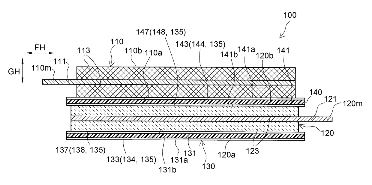
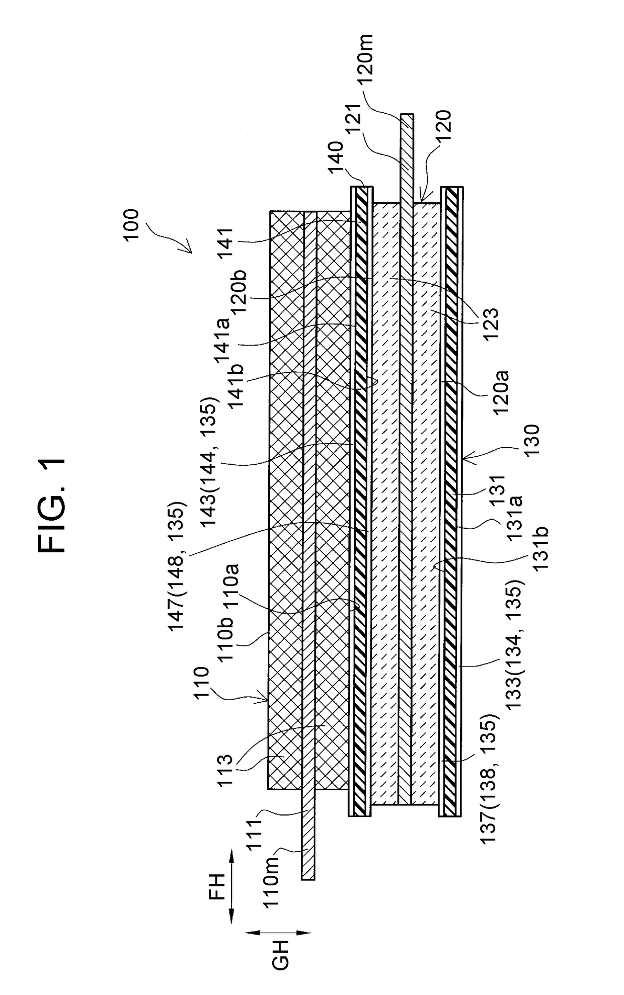
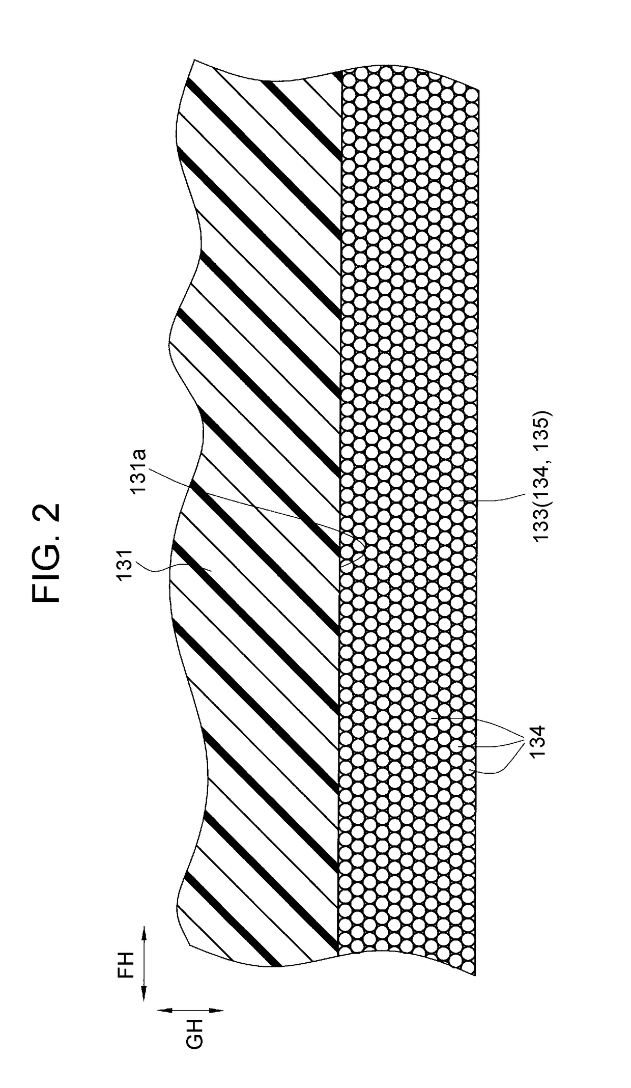
[0032]An embodiment of the present disclosure will be described below with reference to the drawings. FIG. 1 is a sectional view of an electrode stack 100 according to the embodiment. FIG. 2 is a partially enlarged sectional view of the electrode stack 100, showing a first bonding layer 133 and its vicinity, and FIG. 3 is a partially enlarged sectional view thereof, showing a second bonding layer 143 and its vicinity. FIG. 4 shows an electrode assembly 20 formed by stacking a plurality of electrode stacks 100. FIG. 5 and FIG. 6 are respectively a perspective view and a sectional view of a battery 1 including the electrode assembly 20. For the following description, a short-side direction EH, a long-side direction FH, and a thickness direction GH of the electrode stack 100 are defined as the directions indicated in FIG. 1 to FIG. 6. Moreover, for the following description, a battery short-side direction BH, a battery long-side direction CH, and a battery thickness direction DH of the...


PUM

PropertyMeasurementUnit
particle sizeaaaaaaaaaa
thicknessaaaaaaaaaa

Abstract

Provided is an electrode stack formed by integrating a first separator, a first electrode plate, a second separator, and a second electrode plate. The first separator has a first separator body, and a first bonding layer that is formed on a principal surface of the first separator body and contains first polyethylene particles. The second separator has a second separator body, and a second bonding layer that is formed on a principal surface of the second separator body and contains second polyethylene particles. The number of particles of the first polyethylene particles per unit area of the first bonding layer is larger than the number of particles of the second polyethylene particles per unit area of the second bonding layer.

Description

INCORPORATION BY REFERENCE[0001]The disclosure of Japanese Patent Application No. 2017-089367 filed on Apr. 28, 2017 including the specification, drawings and abstract is incorporated herein by reference in its entirety.BACKGROUND1. Technical Field[0002]The present disclosure relates to an electrode stack having a first separator, a first electrode plate, a second separator, and a second electrode plate stacked in this order and integrated, and to a manufacturing method of a battery including a stacked electrode assembly formed by stacking a plurality of such electrode stacks.2. Description of Related Art[0003]A stacked electrode assembly formed by alternately stacking pluralities of positive electrode plates and negative electrode plates having rectangular shapes etc. with a separator therebetween is known as a type of an electrode assembly of a battery such as a lithium-ion secondary battery. For example, such a stacked electrode assembly is manufactured by the following method: A...

Claims


Application Information

Patent Timeline
Patent Type & Authority Applications(United States)
IPC IPC(8): H01M10/04H01M10/0585H01M2/16H01M4/139
CPCH01M10/0468H01M10/0413H01M10/0585H01M2/168H01M4/139B32B2457/10H01M2220/20H01M10/0525H01M4/13H01M10/0431H01M50/461Y02E60/10Y02P70/50
Inventor KUHARA, TAKAHIRO
Owner TOYOTA JIDOSHA KK
Why Eureka
Try Eureka