
Sampling rate synchronization between transmitters and receivers

a technology of synchronizing the sampling rate and the receiver, applied in the field of communication systems, can solve the problems of affecting the sampling rate, and affecting the accuracy of data demodulation

Active Publication Date: 2018-11-01
OLYMPUS CORP
View PDF3 Cites 13 Cited by
  • Summary
  • Abstract
  • Description
  • Claims
  • Application Information

AI Technical Summary

Benefits of technology

The patent text describes a technology solution for estimating timing offsets and synchronizing sampling rates for wireless transmitters and receivers. A wireless receiver can digitally synchronize its receive sampling rate to the transmitter's sampling rate using a sampling rate converter and a timing control unit. The timing control unit calculates and outputs parameters to the sampling rate converter, which in turn adjusts the read pointer in the buffer to compensate for the timing offset. The technology can improve the accuracy of wireless communication by correcting for timing offsets and ensuring synchronization between transmitter and receiver.

Problems solved by technology

Typically, transmitter and receiver sampling clocks have some frequency mismatch, which leads to a sampling rate mismatch and hence may degrade modem performance.
That sampling mismatch is accumulated over the data packet time frame and, if significant, can interfere with precise data demodulation.
These methods require additional analog circuits, which are more expensive and less convenient to use as compared to digital-domain solutions.
In addition, the precision of such methods is limited and in some cases, analog-domain timing synchronization is not possible such as in case of asynchronous frequency-multiplexed signals.
A drawback of this method is the requirement to maintain a plurality of filter coefficients.

Method used


Image

  • Sampling rate synchronization between transmitters and receivers
  • Sampling rate synchronization between transmitters and receivers
  • Sampling rate synchronization between transmitters and receivers

Examples


Embodiment Construction

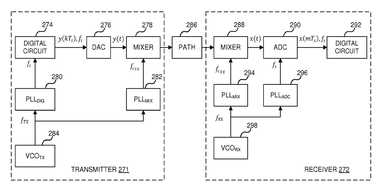
[0023]According to various embodiments of the disclosed technology solutions are presented to provide timing offset estimation, and sampling rate synchronization for wireless transmitters and receivers. Systems and methods are provided in which a wireless receiver can be configured to digitally synchronize a receive sampling rate to a transmit sampling rate, and may include a digital interpolator controlled by a timing control unit with a timing offset estimator. The timing control unit can be configured to calculate and output parameters to the digital interpolator. The digital interpolator can include a sample buffer followed by a fractional delay filter. Output parameters to the digital interpolator can include a fractional delay timing offset signal of the receiver relative to a transmitter timing signal and a buffer pointer control signal to control a position of the read pointer relative to a write pointer to at least partially compensate, for the timing offset. The timing off...


PUM


Abstract

Systems and methods are provided in which a wireless receiver can be configured to digitally synchronize a receive sampling rate to a transmit sampling rate, and may include a digital interpolator controlled by a timing control unit with a timing offset estimator. The timing control unit can be configured to calculate and output parameters to the digital interpolator. The digital interpolator can include a sample buffer followed by a fractional delay filter. Output parameters to the digital interpolator can include a fractional delay timing offset signal of the receiver relative to a transmitter timing signal and a buffer pointer control signal to control a position of the read pointer relative to a write pointer to compensate for subsample timing offset. The timing offset estimator can be configured to calculate and provide to the timing control unit a sampling period ratio control word and an instantaneous timing offset control word.

Description

CROSS-REFERENCE TO RELATED PATENT APPLICATIONS[0001]This application is a U.S. National Stage Application under 35 U.S.C. 371 of International Application No. PCT / US15 / 38135, filed on Jun. 26, 2015, the complete disclosures of which are hereby incorporated by reference.TECHNICAL FIELD[0002]The disclosed technology relates generally to communication systems, and more particularly, some embodiments relate to systems and methods for sampling rate synchronization between transmitters and receivers, in some cases with subsample timing offset estimation.DESCRIPTION OF THE RELATED ART[0003]Wireless communication devices have become ubiquitous in today's society. Indeed, with the many continued advancements in communication technology, more and more devices are being introduced in both the consumer, commercial, and government sectors with advanced communications capabilities. Additionally, advances in processing power and low-power consumption technologies, as well as advances in data codin...

Claims


Application Information

Patent Timeline
IPC IPC(8): H04L7/00H04B1/16H03H17/00H03H17/06
CPCH04L7/0029H04L7/005H04B1/16H03H17/0027H03H17/0642H04L1/1887
Inventor GUDOVSKIY, DENIS A.CHU, LICHUNGLEE, SHINHAENG
Owner OLYMPUS CORP
Learn More