
Inverted Injection Method of Affixing a Termination to a Tensile Member

a technology of tensile members and terminations, which is applied in the direction of mechanical equipment, cables for vehicles/pulleys, ropes and cables, etc., can solve the problems of potting compound void formation, long time-consuming and laborious, and difficult to organize, so as to reduce or eliminate the formation of voids, improve the alignment of strands and load distribution

Active Publication Date: 2018-11-08
BRIGHT TECH CO LTD
View PDF0 Cites 8 Cited by
  • Summary
  • Abstract
  • Description
  • Claims
  • Application Information

AI Technical Summary

Benefits of technology

The patent text discusses a process to improve the alignment and distribution of loads in a cable. This is achieved by controlling the translation ( pulling) of the cable during solidification, which can be accompanied by rotation. The patent also addresses the issue of voids that can form during the translation process and proposes various methods to prevent them. The technical effect of this patent text is better load distribution and improved cable performance.

Problems solved by technology

The filaments are very strong in tension, but they are not very rigid.
These facts make such synthetic filaments difficult to handle during the process of adding a termination and difficult to organize.
As is known to those skilled in the art, an extended length of time may be needed for the potting compound to reach full strength.
Of course, if enough tension is applied the termination will fail.
Once the filaments are placed within the cavity in the anchor, it is very difficult to control their orientation with any specificity.
However, each individual filament tends to bend and slew in a random fashion.
It is not possible to neatly arrange the filaments because there is no way to grip and hold them.
Another known problem is the difference in the filament-to-potting-compound ratio for different regions of the cavity.
Some heat is often desirable, but too much heat tends to produce short polymer-chain length and can create an overheated situation.
For synthetic filaments, however, heat transfer is limited.
When the liquid potting compound begins to heat up in a given area, its viscosity typically drops and it tends to ooze and fill voids more readily.

Method used


Image

  • Inverted Injection Method of Affixing a Termination to a Tensile Member
  • Inverted Injection Method of Affixing a Termination to a Tensile Member
  • Inverted Injection Method of Affixing a Termination to a Tensile Member

Examples


Embodiment Construction

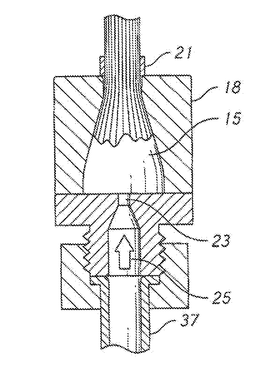
[0134]The present invention presents a new approach to introducing the potting compound used in potted termination. FIGS. 7 and 8 illustrate the basic principles. The cable filaments are placed within cavity 20 of anchor 18 as before. However, the cable and anchor are inverted as shown in the view (inversion may occur at any suitable point in the process). Distal end 56 of anchor 18 faces downward and proximal end 54 feces upward. The orientation is significant to the invention.

[0135]While the inverted orientation is maintained, pressurized liquid potting compound is injected into cavity 20. This may be done in a wide variety of ways. In the embodiment of FIG. 7, sealer 64 has been used to close the open distal end of anchor 18. Sealer 64 includes features to facilitate the injection of the polling compound. Feed line 37 leads to runner 25 which leads to orifice 23. Pressurized liquid potting compound is fed through teed line 37 and into cavity 20 via orifice 23.

[0136]The term “inve...


PUM

PropertyMeasurementUnit
Lengthaaaaaaaaaa
Tensionaaaaaaaaaa
Tensile strengthaaaaaaaaaa

Abstract

A method for attaching an anchor to an end of a tensile member by inverting the assembly of anchor and tensile member and injecting pressurized potting compound. A length of filaments of the tensile member are placed within a cavity through the anchor. The anchor and filaments are placed in an inverted position, with the distal end of the anchor facing downward and the cable extending upward out of the anchor. If the anchor has an open distal end this is sealed. Liquid potting compound is injected into the anchor cavity and allowed to solidify. During the solidification process, a controlled translation (pulling) of the cable is preferably introduced.

Description

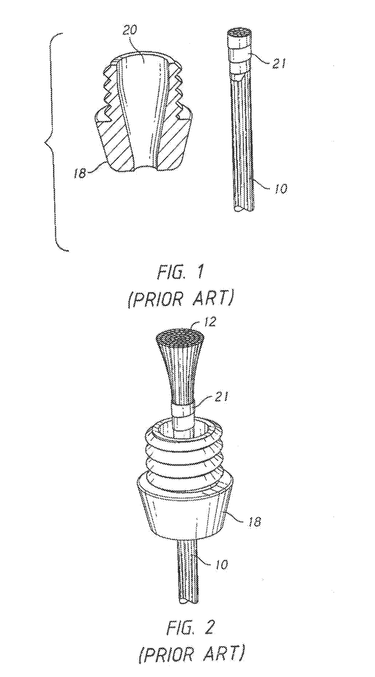
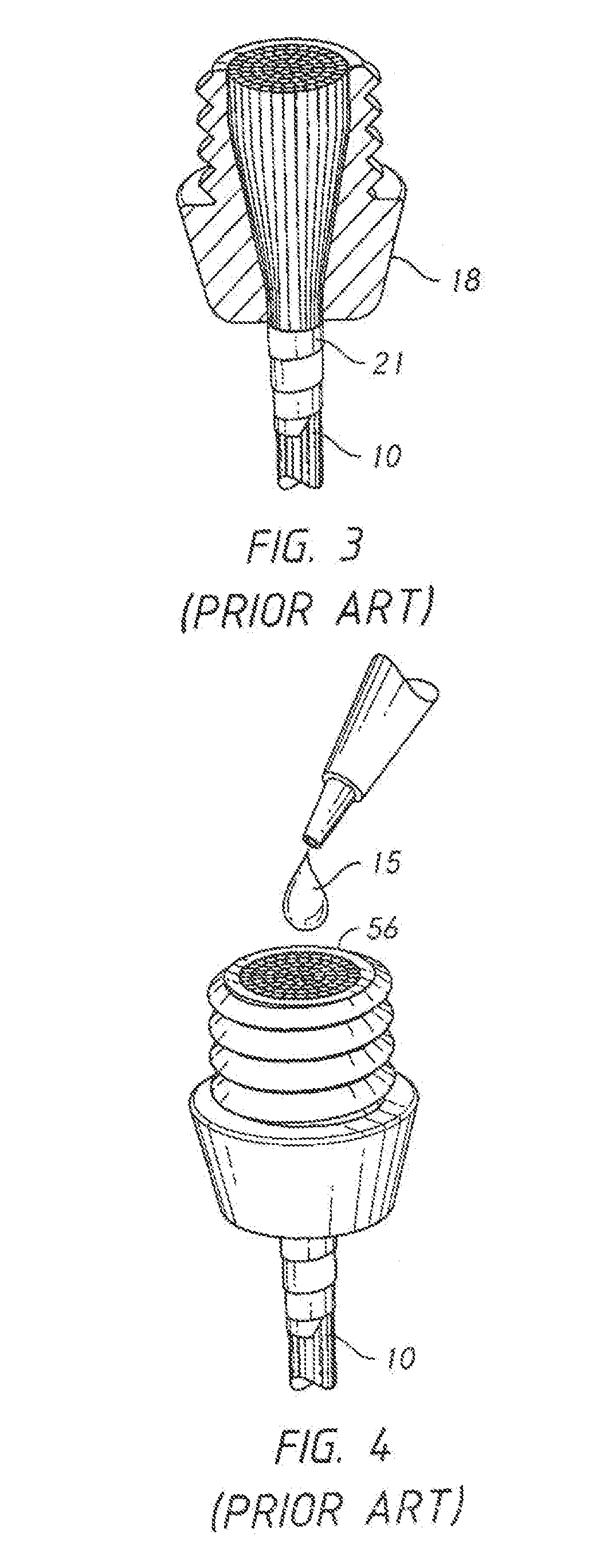
CROSS-REFERENCES TO RELATED APPLICATIONS[0001]This -non-provisional patent application claims the benefit of an earlier-filed provisional application. The first provisional application was assigned Ser. No. 62 / 398,716.STATEMENT REGARDING FEDERALLY SPONSORED RESEARCH OR DEVELOPMENT[0002]Not Applicable.MICROFICHE APPENDIX[0003]Not ApplicableBACKGROUND OF THE INVENTION1. Field of the Invention[0004]This invention relates to the field of tensile strength members. More specifically, the invention comprises a method for affixing a termination to an end of a tensile strength member such as a cable.2. Description of the Related Art[0005]Tensile strength members must generally be connected to other components in order to be useful. A flexible cable provides a good example. The cable mast generally include some type of end-fitting so that it can transmit a load. For example, a cable used in a hoist generally includes a lifting hook on its free end. This lilting hook may be rigged to a load. T...

Claims


Application Information

Patent Timeline
IPC IPC(8): F16G11/04B29C45/14B29C70/84B29C70/88D07B1/00D07B9/00
CPCF16G11/04B29C45/14385B29C45/14426B29C70/84B29C70/88D07B1/005D07B9/00F16G11/042B29C45/14262B29C65/00B29C70/443B29C70/68B29C70/86B29C2045/14278
Inventor CAMPBELL, RICHARD V.GLADWIN, DAVID
Owner BRIGHT TECH CO LTD
Learn More